What You Will Build
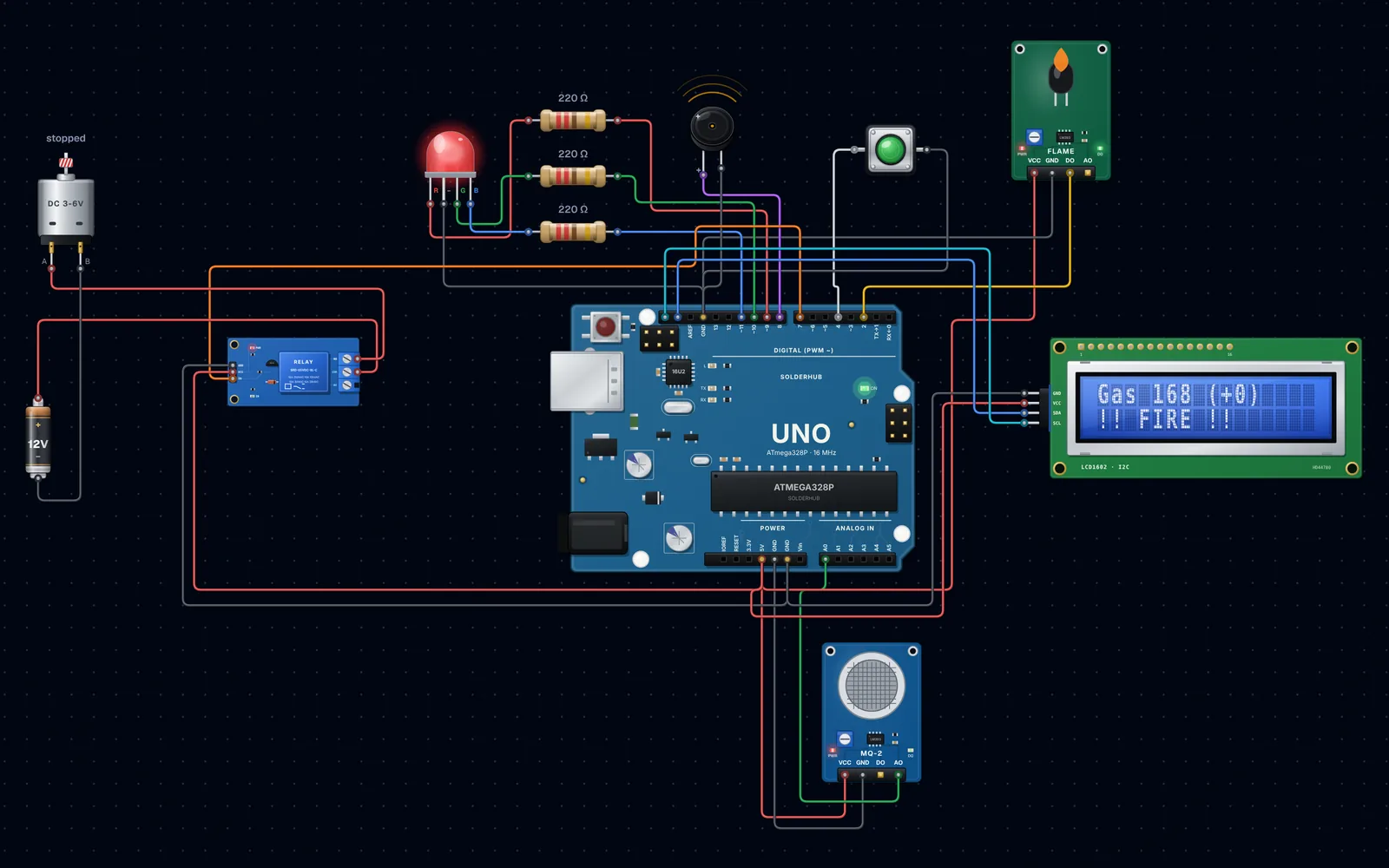
Quick answer: connect the MQ-2's AO to A0, a flame sensor's DO to D2, an RGB LED to D9/D10/D11, a buzzer to D8, a relay to D7 and an I2C LCD to A4/A5. After a short warm-up the sketch learns the clean-air level, then raises WARNING when gas rises 150 counts above it and DANGER at 300 counts or on any flame.
Most MQ-2 tutorials compare the reading with a fixed number, which fails as soon as the room, the sensor or the season changes. This build works more like a commercial detector:
- Clean-air calibration at start-up, with a cap so it never learns a polluted room as "normal"
- Three levels: SAFE (green), WARNING (amber, slow beep, fan on) and DANGER (flashing red, fast siren)
- Fire logic: a flame always means DANGER but keeps the fan off, so it never feeds a fire with air
- Alarm hold: the alarm stays on for 10 s after the reading clears, so it cannot flicker
- Mute button silences the siren for 60 s while the lights keep warning
Components
10 itemsNeed these parts? Get this build sheet by email
Parts list with buy links, plus new builds as they're published. By subscribing you agree to our Privacy Policy. Unsubscribe anytime.
⚠️ Warning
This is a learning project, **not** a certified safety device. Do not rely on it to protect people or property. Use a certified gas and smoke alarm for that. Never test with an open gas supply; a lighter's unlit gas held near the sensor for a second is enough. If the relay ever switches mains voltage, use an enclosed, rated module and have the mains side checked by someone qualified.
How It Works
The MQ-2 Sensor
Inside the MQ-2 is a tin-dioxide element on a small heater. In clean air the element has a high resistance; combustible gases such as LPG, propane, methane and hydrogen, and smoke, lower it. The module turns that into a voltage on AO, so the analog reading rises as gas increases.
Three facts shape the code:
| Fact | Consequence in the sketch |
|---|---|
| The heater needs time to stabilise (about a minute after power-up, and 24 to 48 h when brand new) | A warm-up period before any alarm, with the blue LED blinking |
| The clean-air reading differs between sensors and rooms | The baseline is measured, not hard-coded |
| The heater draws about 150 mA | Power the module from 5V, never from a GPIO pin |
The simulator uses a 10 s warm-up so you are not kept waiting. On hardware, set WARMUP_MS to 60000 or more.
The Flame Sensor
The flame module has an infrared photodiode tuned to the 760 to 1100 nm light flames give off, and an LM393 comparator. Its DO pin goes LOW when a flame is seen; the blue trimmer sets the sensitivity. Sunlight and halogen lamps contain the same infrared, so point it away from windows.
Alarm Levels
| Level | Trigger | RGB LED | Buzzer | Exhaust fan |
|---|---|---|---|---|
| SAFE | Gas within 150 counts of baseline | Green | Off | Off |
| WARNING | Gas 150 to 299 above baseline | Amber | Short beep every 1.5 s | On |
| DANGER (gas) | Gas 300 or more above baseline | Flashing red | Fast siren | On |
| DANGER (fire) | Flame seen | Flashing red | Fast siren | Off |
The level rises immediately but only falls after 10 s without the trigger, a simple form of hysteresis that keeps the alarm stable.
Try It in the Simulator First
Run the circuit below. Wait for the 10 s warm-up, then open the MQ-2 settings and raise the smoke level: first to WARNING with the fan on, then to DANGER. Set the flame sensor's flame strength high and see the fan stop while the siren continues. Press the green button to mute.
Try it in the simulator
Wiring
| Part | Part pin | Arduino Uno |
|---|---|---|
| MQ-2 | VCC / GND | 5V / GND |
| MQ-2 | AO | A0 |
| Flame sensor | VCC / GND | 5V / GND |
| Flame sensor | DO | D2 |
| Mute button | One side / other side | D4 / GND |
| RGB LED | Red / Green / Blue (each via 220 Ω) | D9 / D10 / D11 |
| RGB LED | Common cathode (longest leg) | GND |
| Buzzer | + / − | D8 / GND |
| Relay module | IN / VCC / GND | D7 / 5V / GND |
| Relay contacts | COM / NO | 12 V supply + / fan + |
| Fan | − | 12 V supply − |
| LCD I2C | VCC / GND / SDA / SCL | 5V / GND / A4 / A5 |
The RGB legs use D9, D10 and D11 because they are PWM pins, which lets the sketch mix amber from red and green. Many relay modules are active-LOW (the relay clicks when IN is LOW). If yours switches the wrong way, swap HIGH and LOW in the digitalWrite(RELAY_PIN, ...) line.
The Code
Only LiquidCrystal I2C needs installing. The mute button uses the Uno's internal pull-up, so it needs no resistor.
Key Parts of the Code Explained
| Code | What it does |
|---|---|
readGas() | Averages eight ADC readings to remove noise |
warmUp() | Waits for the heater, averages the second half of the warm-up as the clean-air baseline |
if (baseline > 300) baseline = 300 | Refuses to learn a polluted room as normal |
classify() | Turns the rise above baseline and the flame input into SAFE, WARNING or DANGER |
seen > level / now - lastAlarmSeen >= HOLD_MS | Escalates at once, de-escalates only after 10 s |
bool fan = (level != SAFE) && !flame | Ventilates gas but never blows air at a fire |
muted and MUTE_MS | Silences the siren for 60 s; the lights keep warning |
Upload and Test
- Upload and watch the LCD count down the warm-up while the LED blinks blue.
- Read the baseline in the Serial Monitor at 9600 baud. It is typically 100 to 250 in clean air.
- Test each level and tick the result.
| Test | Expected |
|---|---|
| Clean air after warm-up | Green, SAFE, fan off |
| Unlit lighter gas near the MQ-2 for 1 s | Amber or red, GAS WARNING or !! GAS DANGER !!, fan on |
| Gas cleared | Alarm holds 10 s, then All clear in Serial |
| Lighter flame 30 cm from the flame sensor | Flashing red, !! FIRE !!, fan off |
| Press mute during an alarm | Buzzer stops, MUT on the LCD, lights continue |
Adjust the flame sensor's trimmer so a lighter at 30 to 50 cm triggers it but room lights do not.
Troubleshooting
| Problem | Likely cause | Fix |
|---|---|---|
| Baseline over 300 at every start | Sensor still new, or genuinely dirty air | Run it powered for 24 to 48 h once; ventilate the room |
| Readings drift upward for minutes | Heater not settled | Increase WARMUP_MS to 60 to 120 s |
| False WARNING with no gas | Alcohol, aerosol, cooking fumes, humidity | The MQ-2 reacts to them; raise WARN_RISE |
| Flame alarm in daylight | Infrared from the sun or a halogen lamp | Turn the trimmer down and shade the sensor |
| Relay works backwards | Active-LOW relay module | Invert the relay digitalWrite |
| Amber looks yellow or green | LED colours differ | Change the setRgb(255, 90, 0) mix |
| Uno resets when the fan switches | Fan noise on the 5 V rail | Separate fan supply; add a flyback diode across the fan |
Make It Your Own
- Remote alert: move to an ESP32 and send a Telegram or MQTT message on DANGER.
- More gases: add an MQ-7 for carbon monoxide or an MQ-135 for air quality.
- Gas valve: drive a normally-closed 12 V solenoid valve that shuts on DANGER.
- Event log: record each alarm with a DS3231 timestamp.
- Self-test button: hold it for 3 s to run every output in turn.
FAQ
How long does the MQ-2 need to warm up?
About a minute after each power-up before readings are stable, and 24 to 48 hours of continuous power the first time you use a new sensor. Readings during that burn-in are unreliable.
What does the MQ-2 detect?
LPG, propane, butane, methane, hydrogen, alcohol vapour and smoke. It cannot tell them apart and it does not measure exact concentrations without careful calibration.
Why calibrate in clean air instead of using a fixed threshold?
Every MQ-2 has a different clean-air resistance and the reading changes with temperature and humidity. Measuring the baseline at start-up makes the thresholds work across sensors and rooms.
Why does the fan stay off during a fire?
Fresh air feeds a fire. Ventilation helps disperse leaked gas, so the sketch runs the fan for gas but not for flame.
Can this replace a smoke alarm?
No. It is an educational build with no certification. Always keep a certified smoke and gas alarm installed.
What You Learned
You calibrated an analog sensor against its own baseline, combined two sensors into one alarm state, added hysteresis and a mute, and made a safety-minded output decision. For another air-sensing build see AirWatch air quality monitor, and for relay and pin current limits see the Arduino Uno pinout guide.