What You Will Build
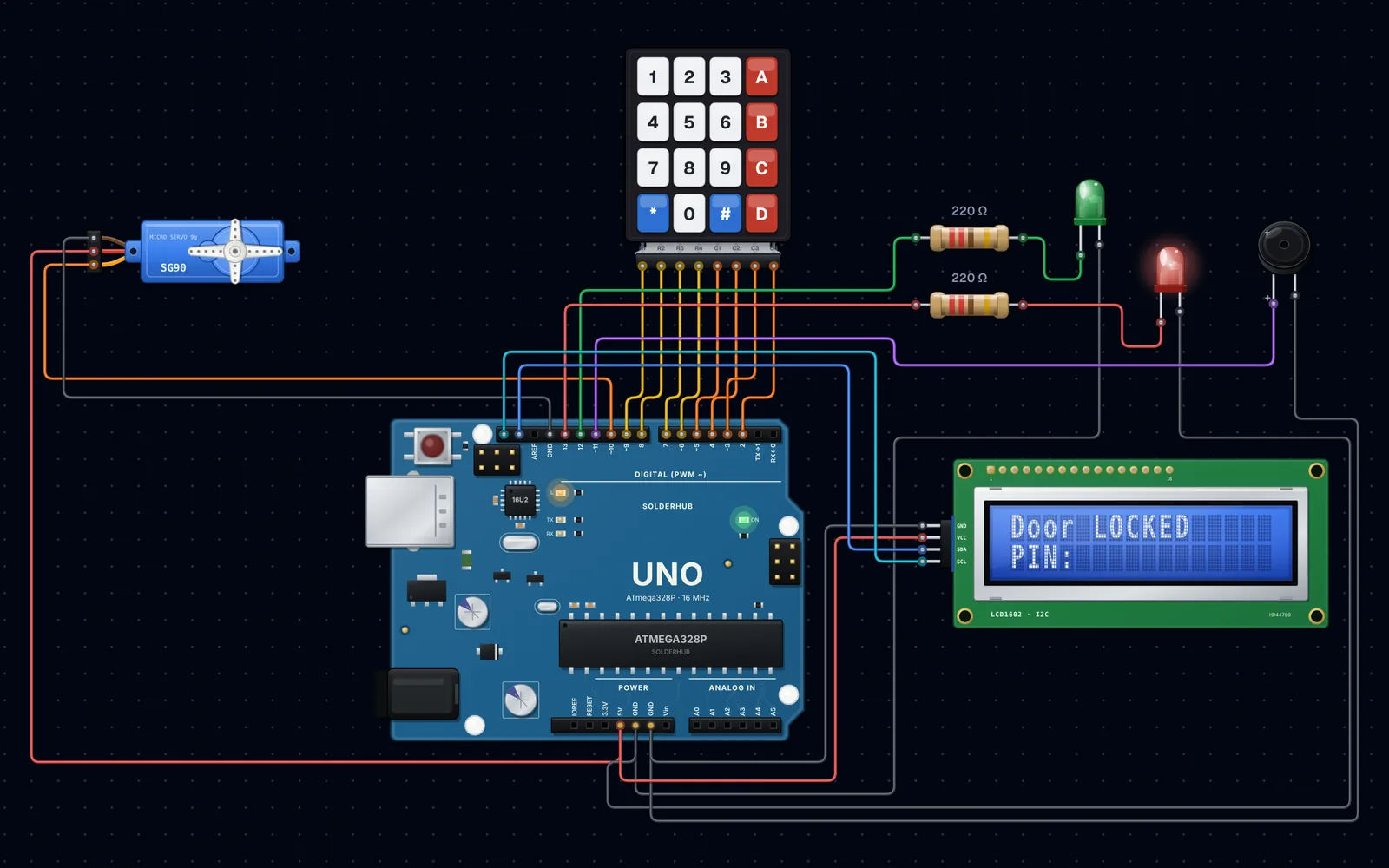
Quick answer: wire a 4x4 keypad to Arduino Uno pins D9 to D2, a servo to D10 and an I2C LCD to A4/A5, then load the sketch below. Type 1234 and press # and the servo swings the bolt open for five seconds. Three wrong PINs block the keypad for 30 seconds.
This is the classic keypad lock, built the way a real product would behave rather than the bare demo most tutorials stop at:
- Masked entry: the LCD shows
****, never the digits #to confirm,*to clear, like a real door panel- Auto re-lock five seconds after opening
- Lockout: three wrong PINs disable the keypad for 30 seconds with a countdown
- Change PIN: press A while unlocked and enter a new four-digit code
- Feedback: a key click, a green LED when open and a red LED when locked
You will learn how a matrix keypad is scanned with only eight wires, how to build the program as a small state machine, and how to drive a servo and an I2C display from the same sketch without one blocking the other.
Components
9 itemsNeed these parts? Get this build sheet by email
Parts list with buy links, plus new builds as they're published. By subscribing you agree to our Privacy Policy. Unsubscribe anytime.
⚠️ Warning
A small SG90 is fine for a drawer latch or a cabinet demo, but it is **not** a security device. For a real door use a 12 V solenoid lock or an electric strike switched by a relay or MOSFET, keep a mechanical override, and never make the lock the only way out of a room.
How a 4x4 Keypad Is Read
A 16-key membrane keypad has no chip inside. It is a grid of four row wires crossing four column wires, and each key simply joins one row to one column when pressed. That is why it needs only 8 pins instead of 16.
The Keypad library scans the grid hundreds of times a second:
- Every row pin is set as an input with its internal pull-up, so it reads HIGH.
- One column at a time is driven LOW.
- If a key in that column is held, its row is pulled LOW too, and the library knows exactly which key it is.
- The column is released and the next one is driven LOW.
| Keypad pin | Function | Uno pin |
|---|---|---|
| 1 (R1) | Row 1: 1 2 3 A | D9 |
| 2 (R2) | Row 2: 4 5 6 B | D8 |
| 3 (R3) | Row 3: 7 8 9 C | D7 |
| 4 (R4) | Row 4: * 0 # D | D6 |
| 5 (C1) | Column 1: 1 4 7 * | D5 |
| 6 (C2) | Column 2: 2 5 8 0 | D4 |
| 7 (C3) | Column 3: 3 6 9 # | D3 |
| 8 (C4) | Column 4: A B C D | D2 |
Pin 1 is usually on the left when the keys face you, but cheap keypads vary. If keys come out wrong, the troubleshooting section shows how to fix the mapping in code instead of rewiring.
The Lock as a State Machine
The sketch is always in exactly one of four states, and each key means something different depending on the state:
| State | What the keys do | Leaves the state when |
|---|---|---|
| LOCKED | Digits build the PIN, * clears, # checks it | Right PIN (to UNLOCKED) or third wrong PIN (to LOCKOUT) |
| UNLOCKED | A starts a PIN change, D locks at once | 5 s pass or D is pressed |
| LOCKOUT | Ignored | 30 s pass |
| NEW_PIN | Digits build the new PIN, # saves it | # with four digits |
Writing it this way keeps every rule in one place and makes features like the lockout a few lines rather than a tangle of flags.
Try It in the Simulator First
The complete circuit and sketch run in the SolderHub Simulator below, with the same pins as this guide. Press and hold keys on the keypad itself: type 1 2 3 4 and # and watch the servo turn, the green LED light and the LCD change. Then enter a wrong PIN three times to see the lockout countdown.
Try it in the simulator
Wiring
| Part | Part pin | Arduino Uno |
|---|---|---|
| Keypad | R1 to R4 | D9, D8, D7, D6 |
| Keypad | C1 to C4 | D5, D4, D3, D2 |
| SG90 servo | Signal (orange) | D10 |
| SG90 servo | VCC (red) / GND (brown) | 5V / GND |
| Buzzer | + / − | D11 / GND |
| Green LED | Anode via 220 Ω | D12 |
| Red LED | Anode via 220 Ω | D13 |
| LCD I2C | VCC / GND | 5V / GND |
| LCD I2C | SDA / SCL | A4 / A5 |
D10 is used for the servo because the Servo library takes over Timer1, which also disables PWM on D9 and D10. Neither pin needs PWM here, so nothing is lost.
Powering the Servo
An SG90 can draw over 500 mA for a moment when it starts moving. Powered from the Uno's 5V pin through USB that is usually fine on the bench, but if the LCD flickers or the Uno resets when the bolt moves, power the servo from a separate 5 V supply and join its ground to the Uno's GND. Without a shared ground the signal has no reference and the servo jitters.
The Code
Install two libraries from Sketch → Include Library → Manage Libraries: Keypad by Mark Stanley and Alexander Brevig, and LiquidCrystal I2C by Frank de Brabander. Servo and Wire come with the IDE. If your LCD stays blank, run an I2C scanner and change 0x27 to the address it finds (often 0x3F).
Key Parts of the Code Explained
| Code | What it does |
|---|---|
Keypad keypad = Keypad(makeKeymap(keys), rowPins, colPins, 4, 4) | Tells the library which pins are rows and columns and what each key means |
keypad.getKey() | Returns a key once when it is pressed, or 0 when nothing new happened, and handles debouncing |
enum State { LOCKED, UNLOCKED, LOCKOUT, NEW_PIN } | The four states the lock can be in |
showMasked() | Prints one * per digit typed, so nobody can read the PIN over your shoulder |
strcmp(entry, pinCode) == 0 | Compares the typed PIN with the stored one |
beep(ms) and beepUntil | Starts a beep and lets loop() stop it later, so a beep never freezes the keypad |
now - stateSince >= UNLOCK_MS | Non-blocking timer for the auto re-lock and the lockout |
The new PIN is kept in RAM, so it returns to 1234 after a power cut. To keep it, save it with EEPROM.put() when it changes and read it back in setup().
Upload and Test
- Select Tools → Board → Arduino Uno and the right port, then upload.
- The LCD shows
Keypad Lock v1, thenDoor LOCKEDandPIN:. The red LED is on. - Work through the table below and tick each result.
| You do | LCD | LEDs and servo |
|---|---|---|
| Type 1 2 3 | PIN: *** | Red on, servo at 0° |
Press * | PIN: cleared | No change |
| Type 1 2 3 4 # | Access granted / A:new PIN D:lock | Green on, servo at 90°, beep |
| Wait 5 s | Door LOCKED | Red on, servo back to 0° |
| Wrong PIN + # (1st, 2nd) | Wrong PIN / 2 tries left | Long beep |
| Wrong PIN + # (3rd) | Too many tries / Wait 30 s | Red blinks, keys ignored |
| Unlock, press A, type 4 new digits, # | PIN changed | Next unlock needs the new PIN |
Fit the servo horn so that 0° is the locked position before you fix it to the bolt, then adjust LOCKED_ANGLE and UNLOCKED_ANGLE in a few degrees at a time.
Troubleshooting
| Problem | Likely cause | Fix |
|---|---|---|
| Wrong characters appear | Keypad pinout differs | Swap the order in rowPins or colPins, or swap rows and columns entirely |
| A whole row or column never works | Loose ribbon contact | Press the 8-pin connector fully onto the header pins |
| Same digit appears twice | Very worn membrane | The library debounces 10 ms; raise it with keypad.setDebounceTime(30) |
| LCD backlight on, no text | Wrong I2C address or contrast | Run an I2C scanner, then turn the blue trimmer on the backpack |
| Uno resets when the servo moves | Supply dip | Power the servo from its own 5 V supply with a shared ground |
| Servo buzzes at rest | Horn pushing against an end stop | Reduce the angle range by a few degrees |
| New PIN lost after power off | Stored in RAM only | Save it to EEPROM as described above |
Make It Your Own
- Real lock: swap the servo for a 12 V solenoid through a relay module and a separate supply.
- Keep the PIN: store it in EEPROM, with a factory-reset key combination.
- Two-factor: add an RC522 RFID reader and require card and PIN.
- Alarm: after a lockout, sound the buzzer continuously until a master code is entered.
- Log: add a DS3231 clock and print each access with a timestamp to the Serial Monitor.
FAQ
How many pins does a 4x4 keypad need on Arduino?
Eight: four rows and four columns. The keypad is a passive grid, so the Arduino finds a key by driving one column LOW at a time and checking which row follows it.
Do I need resistors on the keypad?
No. The Keypad library turns on the Uno's internal pull-up resistors on the row pins, so the keypad connects directly.
Why does my keypad print the wrong numbers?
The pinout of cheap keypads varies. Change the order of the pins in rowPins and colPins until each key matches, which is quicker than rewiring.
Can I use a 4x3 keypad?
Yes. Set COLS to 3, remove the last column from the key map, and use seven pins. You lose the A to D keys, so move the change-PIN function to another key.
Is a servo strong enough for a real door?
No. Use it for boxes, drawers and demos. A real door needs a solenoid lock or an electric strike with its own power supply and a manual override.
What You Learned
You scanned a key matrix with eight wires, organised a sketch as a state machine and kept the timing non-blocking. For a card-based version of the same idea see the Arduino RFID door lock, and for the Uno's pins and current limits see the Arduino Uno pinout guide.