Components
9 itemsHow to Build a Gesture Controlled Robotic Arm (4 DOF) So first things first, you want to gather all your components before anything else. You need a 4 DOF robotic arm chassis (the laser-cut wooden kind), 4 servo motors, an MPU6050 accelerometer sensor, a PCA9685 16-channel servo driver, an Arduino Uno, a 5V DC power source, 2 full-size breadboards, 1 mini breadboard, a push button module, a toggle switch, a 100 microfarad capacitor, jumper wires both male-to-male and male-to-female, and a glove for one hand.
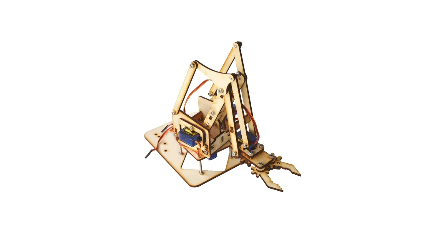
Assembling the Chassis Start with the robotic arm chassis. Sort out all the laser-cut wooden pieces first so you know what you are working with. Then start screwing and bolting the joints together. Each joint has a slot for a servo motor so make sure you fix the servos in place as you go, do not leave them for later. Now the claw mechanism is the part that will confuse you the most. The gear linkage is not obvious from just looking at it so do yourself a favour and look up a video specific to your chassis build before you start forcing pieces together. The one that helped us was this: https://youtu.be/n3G2YBZq3PQ. If your kit comes short on bolts which ours did, just redistribute what you have and make sure the load-bearing joints at the base and shoulder are the most secure ones. Those are the ones taking the most stress. Setting Up the Power Supply Take your 5V DC source and connect the positive output through the toggle switch first, then from the other switch terminal into the positive rail of your breadboard. The negative output of the DC source goes directly into the negative rail. Put the 100 microfarad capacitor across those rails as well, longer leg to positive and shorter leg to negative. This absorbs voltage spikes from the servo motors and keeps the rail stable during operation. Since the 5V DC source already outputs a clean regulated voltage, you do not need to measure or adjust anything. Just confirm the output is 5V before connecting your components. Anything significantly above that will damage your servo motors.
Wiring Everything Together Now for the connections. All your components share a common ground, this is not optional, if you skip this you will get erratic readings and I2C errors. Connect the Arduino GND, the PCA9685 GND side pin and terminal block GND, the MPU6050 GND, and the push button GND all to the negative rail on the breadboard. From the breadboard positive rail, connect to the V+ terminal block on the PCA9685. This is the high-power path for the servo motors. Do not power the servos from the Arduino 5V pin, the Arduino cannot handle that current and it will keep resetting on you. For logic power, connect the Arduino 5V pin to the VCC of the PCA9685, the VCC of the MPU6050, and the V pin of the push button module. These all share the same 5V logic supply from the Arduino. For powering the Arduino itself, connect the 5V DC source positive rail to the Arduino VIN pin and the negative rail to the Arduino GND. The Arduino's onboard regulator will handle the rest for logic power. For the I2C bus, connect Arduino A4 to the SDA pin on both the PCA9685 and the MPU6050. Connect Arduino A5 to the SCL pin on both. You do this by running horizontal connections across the breadboard so one Arduino pin reaches both devices at the same time. Then connect the servo for the claw directly to Arduino pin 6 (signal wire) and the push button signal pin to Arduino pin 2. The three remaining servos, base on channel 0, shoulder on channel 1, and elbow on channel 2, all go into the PCA9685 channel slots. Mounting the Sensor on the Glove Glue your mini breadboard to the back of the glove. Mount the MPU6050 onto the mini breadboard and wire it up there. Then run a wire harness with four lines, VCC, GND, SDA, and SCL, from the glove all the way back to your control unit breadboard. Keep the harness long enough to allow free hand movement without pulling on any connections.
Programming the Arduino Open the Arduino IDE. Install the Adafruit PWM Servo Driver Library from the Library Manager. Wire.h and Servo.h are already built in so you do not need to install those. Upload the code. Before you run the full firmware, run an I2C scanner sketch first to confirm your MPU6050 shows up at address 0x68 and your PCA9685 shows up at 0x40. If either of those is missing, check your SDA and SCL connections and make sure your common ground is solid. Once confirmed, upload the main firmware. Open the serial monitor and you should see "System Ready. All systems go." If the loop keeps running and printing that without freezing, your I2C bus is stable. How the Gestures Work Rolling your wrist so the thumb faces up or down controls the base servo on the Y axis. Pitching your hand up and down so the fingers point toward the ceiling or the floor controls the shoulder servo on the X axis. Lifting your entire hand vertically up or down in space controls the elbow servo using the raw Z axis accelerometer data. The push button toggles the claw, first press closes it, second press opens it.
Troubleshooting What Will Likely Go Wrong If your servos jitter, your servo power is coming from the wrong place. Route it through the 5V DC source into the breadboard rail and through the PCA9685 terminal block. If your I2C bus keeps freezing, add Wire.setWireTimeout(3000, true) in your setup function and make sure your 100 microfarad capacitor is on the rails. If your claw opens on power-up by itself and behaves backwards, your push button is active-low. Change your code to trigger on a HIGH to LOW falling edge, not a HIGH state. If your readings are unstable and your servos are moving on their own, your grounds are not connected. Check that every single component shares the same ground rail.


