

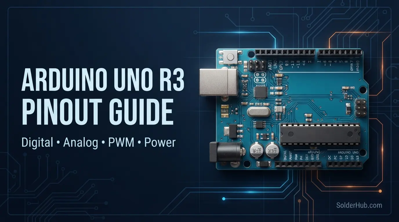
If you've just pulled an Arduino Uno R3 out of the box and you're staring at two rows of pin headers wondering "okay, but which one actually does what?" — you're in exactly the right place, and you're not the first person to feel a little lost here.
Here's the thing about the Uno: it's the board almost everyone starts with, which means it's also the board most people never actually sit down and learn properly. You copy a wiring diagram from a project, it works, you move on. Then three projects later you're trying to figure out why your servo library broke your PWM output, or why your I2C sensor won't talk to the board, and you realize you skipped the fundamentals.
So let's fix that. This is the pin-by-pin breakdown — power, digital, analog, PWM, the works — written the way I wish someone had explained it to me the first time.
What's Actually on the Board
The Uno R3 is built around the ATmega328P — an 8-bit microcontroller running at 16 MHz, with 32 KB of flash memory (about 0.5 KB reserved for the bootloader), 2 KB of SRAM, and 1 KB of EEPROM. That's genuinely tiny by modern standards — your phone's RAM is measured in gigabytes — but it's plenty for the vast majority of hobbyist projects, and the constraint is part of why the Uno forces you to actually understand what your code is doing instead of throwing memory at the problem.
In terms of pins, you're working with 14 digital I/O pins (0–13), 6 analog input pins (A0–A5), and a small cluster of power pins. That's it. No hidden pins, no confusing numbering scheme, no chip variants to worry about. This simplicity is exactly why it's still the reference board almost every tutorial online is written against.
Power Pins
Every project starts with power, so let's get this section out of the way first.
| Pin | Description |
|---|---|
| VIN | Input voltage (7–12V recommended) when powering via an external supply, not USB |
| 5V | Regulated 5V output, sourced from either USB or the onboard regulator |
| 3.3V | Regulated 3.3V output — max ~50mA |
| GND | Ground (multiple GND pins, all connected internally) |
| RESET | Pull LOW to reset the microcontroller |
| IOREF | Reference voltage for shields — reads 5V on the Uno |
A couple of details that trip people up constantly:
VIN is not the same as 5V. If you feed 9V into VIN, the onboard voltage regulator steps it down to 5V for the board and the 5V pin. But if you connect 9V directly to the 5V pin, you skip the regulator entirely and you will let the smoke out. This is one of the most common ways people kill an Uno in their first month.
The 3.3V pin has almost nothing left to give. At 50mA max, it's fine for a single low-power sensor breakout, but connect two or three modules to it and you'll get brownouts, weird resets, or sensors that just refuse to initialize. If you're driving anything more demanding — an nRF24L01 radio module is a classic offender here — use a dedicated 3.3V regulator instead of leaning on the board's pin.
RESET isn't just for the reset button. You can pull this pin LOW in your own circuit (a push button to GND works fine) to trigger a reset programmatically, which is handy for auto-reset circuits or certain bootloader tricks.
Digital I/O Pins (0–13)
These are your general-purpose pins — each one can be configured as either an input or an output using pinMode(). They switch between 0V (LOW) and 5V (HIGH), and each pin can source or sink up to 40mA, though Atmel's own datasheet recommends staying closer to 20mA in practice to avoid heating and long-term degradation of the pin driver.
pinMode(13, OUTPUT);
digitalWrite(13, HIGH);  // Turn the pin on
Six of these fourteen pins do double duty as PWM outputs, and two of them double as external interrupts. Let's get into those.
PWM Pins (~3, ~5, ~6, ~9, ~10, ~11)
You'll spot these by the tilde (~) printed next to the pin number on the silkscreen. PWM — Pulse Width Modulation — is how the Uno fakes an analog output on a digital pin: it switches the pin on and off very rapidly, and the ratio of on-time to off-time (the duty cycle) determines the effective "analog" value your LED, motor, or servo sees.
analogWrite(9, 128); // roughly 50% duty cycle
Here's a detail that catches people out: not all six PWM pins run at the same frequency. Pins 5 and 6 run at roughly 980 Hz, while 3, 9, 10, and 11 run at about 490 Hz. For dimming an LED this difference is invisible. For driving a motor driver or generating audio, it can matter quite a bit, and it's the kind of thing that sends you down a two-hour debugging rabbit hole if you don't already know it's there.
External Interrupts (2 and 3)
Only two pins on the Uno can trigger a hardware interrupt: pin 2 (INT0) and pin 3 (INT1). An interrupt lets your code react the instant a pin changes state, rather than checking it repeatedly inside loop() and possibly missing a fast event.
attachInterrupt(digitalPinToInterrupt(2), myISR, FALLING);
This is the pin pair you want for rotary encoders, precise button debouncing, or catching pulses from a flow sensor or tachometer. If your project needs more than two interrupt-capable pins, that alone is often a sign you've outgrown the Uno and should be looking at a Mega or an ESP32 instead — both of which offer far more interrupt-capable pins.
UART / Serial (Pins 0 and 1)
The Uno has exactly one hardware serial port, and it's shared with the USB connection used for programming and the Serial Monitor.
| Pin | Function |
|---|---|
| 0 | RX (Receive) |
| 1 | TX (Transmit) |
Serial.begin(9600);
Serial.println("Hello from the Uno");
This single-UART limitation is the single biggest practical constraint on the board. If you wire a GPS module or a Bluetooth radio to pins 0 and 1, you can no longer use the Serial Monitor for debugging while that device is connected — they're fighting over the same physical wire. Most people work around this with the SoftwareSerial library, which emulates a second serial port on any two digital pins. It works, but it's not free: SoftwareSerial is CPU-intensive and unreliable at higher baud rates, so treat it as a workaround rather than a real second UART. If you find yourself needing genuinely reliable multiple serial connections, that's exactly the kind of task the Mega's four hardware UARTs were built for.
SPI Pins (10, 11, 12, 13)
SPI is the protocol of choice for fast peripherals — SD cards, TFT displays, and radio modules like the nRF24L01 all typically use it.
| Pin | Function |
|---|---|
| 10 | SS (Slave Select, sometimes called CS) |
| 11 | MOSI (Master Out, Slave In) |
| 12 | MISO (Master In, Slave Out) |
| 13 | SCK (Clock) |
#include <SPI.h>
SPI.begin();
These same four signals are also broken out on the 6-pin ICSP header in the middle of the board, which is how you'd program the ATmega328P directly with a separate programmer, bypassing the bootloader entirely. Most shields wire through the ICSP header rather than the numbered pins, so both routes exist for a reason.
One easy-to-miss detail: pin 13 is also wired to the onboard LED. If you're using SPI and also see your onboard LED flickering with data traffic, that's completely normal — it's the SCK clock signal toggling, not a bug.
I2C Pins (A4 and A5)
I2C lets you connect a whole chain of devices using just two wires — a shared data line and a shared clock line. It's the protocol behind most OLED displays, real-time clocks, IMUs, and a large chunk of sensor breakout boards.
| Pin | Function |
|---|---|
| A4 | SDA (Data) |
| A5 | SCL (Clock) |
#include <Wire.h>
Wire.begin();
Wire.beginTransmission(0x3C);  // typical OLED address
Notice these live on the analog side of the board, not the digital side — a common source of confusion for beginners who go looking for SDA/SCL near the digital pins and can't find them. Each I2C device needs a unique 7-bit address, and most modules ship with default addresses already set (sometimes with solder-jumper pads to change them if you need to run two of the same sensor on one bus). You'll also need pull-up resistors, typically 4.7kΩ, on both SDA and SCL — most breakout boards already include them, but bare sensor modules often don't.
Analog Input Pins (A0–A5)
Six analog pins, each feeding a 10-bit analog-to-digital converter, giving you readings from 0 to 1023 mapped across 0V to 5V.
int sensorValue = analogRead(A0);
float voltage = sensorValue * (5.0 / 1023.0);
All six can also be used as regular digital I/O if you run short of the fourteen digital pins — they map internally to digital pins 14 through 19. It's a slightly unusual move, but it works fine in a pinch.
Two habits worth building early: don't leave unused analog pins floating (an unconnected analog input picks up ambient electrical noise and gives you unstable, meaningless readings — tie it to GND if it's not in use), and remember that analogRead() isn't instantaneous. Each conversion takes roughly 100 microseconds, which is irrelevant for a single sensor but starts to matter if you're rapidly polling several analog inputs in a tight loop.
AREF — the Pin Everyone Forgets Exists
Tucked at the end of the digital header row, AREF lets you set a custom reference voltage for the analog-to-digital converter instead of the default 5V.
analogReference(EXTERNAL);
Why would you want this? Precision. If you're reading a sensor with a 0–2.5V output range, using the full 5V reference wastes half your resolution — you're only ever using half the ADC's range. Set AREF to 2.5V with analogReference(EXTERNAL) and feed 2.5V into the AREF pin, and suddenly your 10-bit resolution is spread across the sensor's actual output range instead of being half-wasted.
One important safety note: never call analogReference(EXTERNAL) and then leave the AREF pin unconnected, and never apply voltage to AREF before making that call — either mistake can damage the internal reference circuitry.
Practical Pin Usage Tips
Reserve pins 2 and 3 for anything time-critical. If a signal needs an immediate response — an encoder, a fast button, a pulse counter — those are your only two options for true interrupts on this board.
Budget your total current, not just per-pin current. Each pin might handle 40mA individually, but the ATmega328P as a whole has a combined current limit across all I/O pins. Driving several LEDs directly without current-limiting resistors is a fast way to overheat the chip even if no single pin looks "overloaded" on paper.
Don't fight the single UART — plan around it. Decide early whether pins 0/1 are for USB debugging or for a peripheral device, and if you genuinely need both at once, either use SoftwareSerial on spare pins for the low-speed device, or accept that this project has outgrown the Uno.
The onboard LED on pin 13 is genuinely useful for diagnostics, not just the classic blink sketch. A lot of people wire it into their code as a heartbeat indicator — a slow, steady blink that tells you at a glance the main loop is still running and hasn't hung.
Label your GND connections mentally, even though they're all the same net. All ground pins on the board are electrically identical, but keeping your wiring organized (motor grounds separate from sensor grounds where possible, joined at a single point) will save you hours of noise-related debugging down the line, especially with anything drawing meaningful current.
Common Mistakes and How to Avoid Them
Feeding voltage directly into the 5V pin from an external supply. This bypasses the onboard regulator and its protection circuitry. Use VIN for anything above 5V, or power through the barrel jack.
Assuming 3.3V-logic sensors are safe on 5V digital pins. The Uno is a 5V board. Many newer sensor modules (some GPS modules, certain radio transceivers, and most bare ESP-series chips) are 3.3V-only, and connecting them directly to a 5V digital output can damage them over time, even if it seems to "work" at first. Use a logic level shifter.
Forgetting that A0–A5 need pinMode() too when used digitally. If you're repurposing an analog pin as a digital output, it still needs to be explicitly configured — it doesn't happen automatically just because you called digitalWrite().
Ignoring flyback diodes on inductive loads. Relays, solenoids, and small motors generate a voltage spike (back-EMF) the instant they're switched off. Without a flyback diode across the coil, that spike can damage the driving pin or the whole board over repeated cycles.
Overloading the 5V rail when powering from USB. USB ports — especially on laptops — typically cap out around 500mA. If you're powering hungry peripherals (multiple servos, a bright LED strip, several sensor modules) off the board's 5V pin while running from USB, you'll get brownouts and mysterious resets that have nothing to do with your code.
Summary: Uno Pin Reference at a Glance
| Feature | Count / Detail |
|---|---|
| Digital I/O | 14 (pins 0–13) |
| PWM-capable pins | 6 (~3, ~5, ~6, ~9, ~10, ~11) |
| Analog inputs | 6 (A0–A5) |
| External interrupts | 2 (pins 2, 3) |
| Hardware UART | 1 (pins 0, 1) |
| SPI | Pins 10–13, also via ICSP header |
| I2C | A4 (SDA), A5 (SCL) |
| Flash memory | 32 KB |
| SRAM | 2 KB |
| EEPROM | 1 KB |
| Clock speed | 16 MHz |
The Uno's real strength isn't raw specs — plenty of newer boards outclass it on paper. It's that every pin has exactly one clear job, there's no chip-variant confusion, and nearly every tutorial, library, and forum post on the internet assumes you're wiring against this exact layout. Once you've got this pin map in your head, you stop copying wiring diagrams blindly and start understanding why they're wired the way they are — which is the point where you actually start designing your own circuits instead of just replicating someone else's.
Arduino Uno R3 · ATmega328P · 14 Digital Pins · 6 Analog Inputs · 1x UART · SPI · I2C · PWM
Quick Answers to Common Uno Pin Questions
How many pins does the Arduino Uno actually have? Fourteen digital pins (0–13) and six analog pins (A0–A5), for twenty usable I/O pins in total, plus the separate power header (VIN, 5V, 3.3V, GND, RESET, IOREF).
Which pins are PWM on the Uno? Six of them: 3, 5, 6, 9, 10, and 11 — identifiable by the tilde (~) printed next to the pin number.
Can I use analog pins as digital pins? Yes. A0–A5 map internally to digital pins 14–19 and can be used with pinMode() and digitalWrite() exactly like the numbered digital pins.
Is the Uno R3 the same as older Uno revisions? Pin-for-pin, yes — the R3 kept the same functional layout as the R2, with the main changes being the addition of the SDA/SCL pins next to AREF (in addition to A4/A5) and a change to the USB-to-serial chip. Most tutorials written for "the Uno" work across all R-series revisions without modification.
What about the newer Uno R4? The R4 swaps the ATmega328P for a Renesas RA4M1 (ARM Cortex-M4), which changes the internal specs considerably — more flash, more RAM, a faster clock, and a built-in RTC — but Arduino kept the physical pin layout compatible with the R3 so that existing shields still fit. If you're following a pin-numbered tutorial written for the R3, it will generally still apply to the R4, though a few advanced peripheral details (like the ADC resolution, which is higher on the R4) differ under the hood.
Do I need external pull-up resistors for I2C on the Uno? Usually not if you're using a breakout board — most already include them. If you're wiring a bare I2C chip directly, yes, add your own (commonly 4.7kΩ) on both SDA and SCL.
What happens if I use pins 0 and 1 for something other than USB serial? Nothing bad happens electrically, but you lose the ability to use the Serial Monitor for debugging while that peripheral is connected, since both share the same physical UART hardware.
Where to Go From Here
Once the Uno's pin map feels familiar rather than intimidating, the natural next questions are usually about scale — what to do when fourteen digital pins genuinely aren't enough, or when you need more than one hardware serial port running at once. That's the point where boards like the Arduino Mega 2560 or the ESP32 start making sense, not as an upgrade for its own sake, but because the project's pin and memory requirements have actually outgrown what the Uno was designed to offer. Knowing this layout cold is what makes that jump straightforward instead of another round of confused wiring diagrams.