What You Will Build
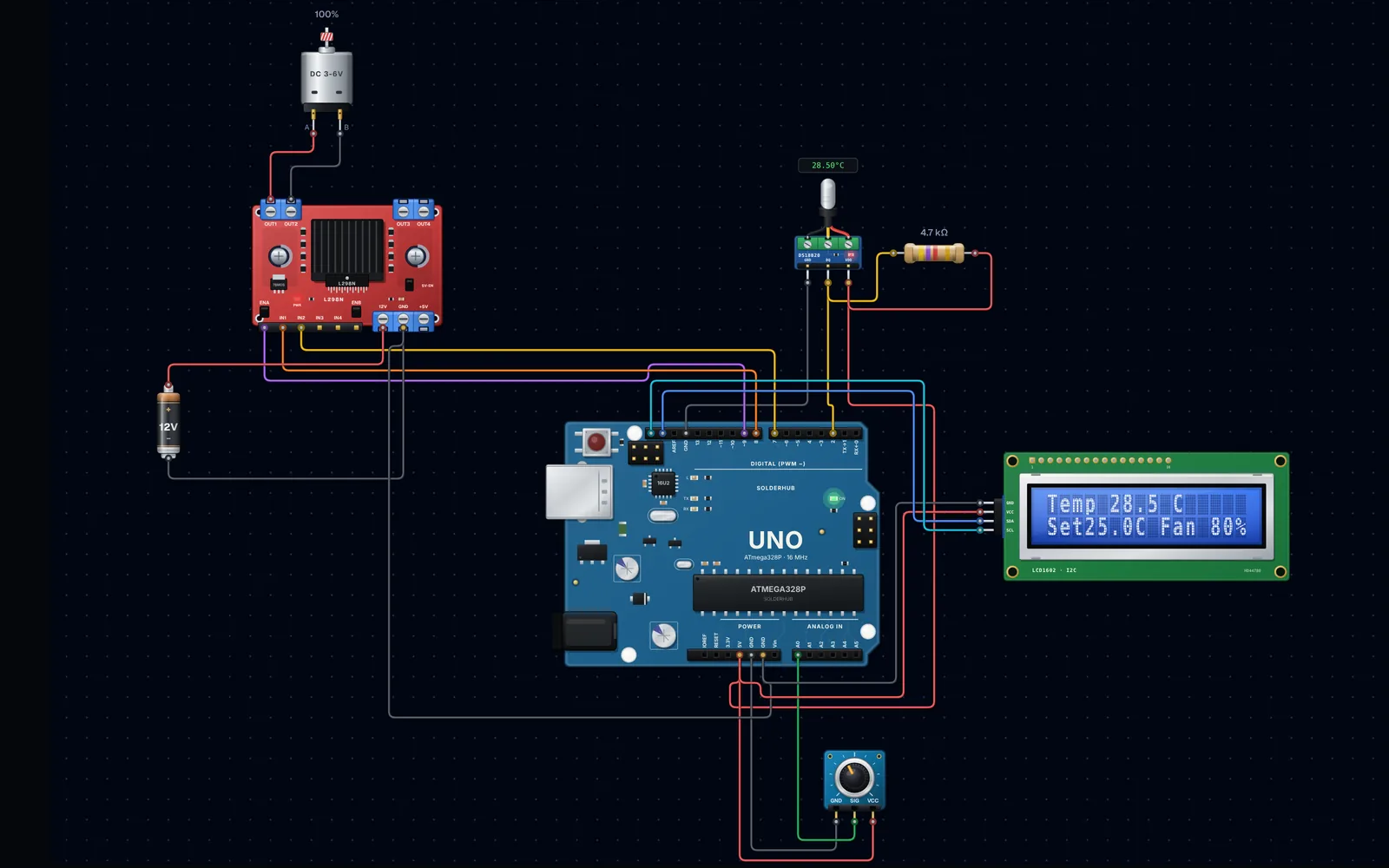
Quick answer: connect a DS18B20 to D2 with a 4.7 kΩ pull-up, a 10 kΩ knob to A0, and an L298N to D9 (ENA), D8 (IN1) and D7 (IN2), with the fan on OUT1/OUT2 and its own 12 V supply. The sketch turns the fan on at the set-point and ramps it from about 35 % to 100 % over the next 5 °C.
A fan that is simply on or off is noisy and wasteful. This controller behaves like a real thermostat:
- Proportional speed: the hotter it gets above the set-point, the faster the fan
- Adjustable set-point from 18 °C to 35 °C on a potentiometer, in 0.5 °C steps
- Hysteresis, so the fan does not chatter on and off around the set-point
- Minimum duty, because a fan will not start below a certain PWM
- Fail-safe: if the sensor is unplugged the fan runs at full speed
- Non-blocking sensor reads, so the knob and display stay responsive
Use it for a 3D-printer enclosure, an electronics cabinet, a reptile tank vent or a greenhouse.
Components
9 itemsNeed these parts? Get this build sheet by email
Parts list with buy links, plus new builds as they're published. By subscribing you agree to our Privacy Policy. Unsubscribe anytime.
⚠️ Warning
Never power the fan from the Arduino. Give the L298N its own 12 V supply, connect that supply's ground to the Uno's GND, and keep the 12 V wire away from the Uno's 5V pin. If the L298N's 5 V regulator jumper is fitted and you feed more than 12 V, remove the jumper and power the module's 5 V logic separately.
How It Works
The DS18B20
The DS18B20 is a digital sensor on a 1-Wire bus: power, ground and a single data line that needs a 4.7 kΩ pull-up to 5 V. It measures −55 °C to +125 °C with ±0.5 °C accuracy between −10 °C and +85 °C. At 12-bit resolution each conversion takes up to 750 ms.
Most examples call requestTemperatures() and wait those 750 ms, which freezes the sketch. Here we call setWaitForConversion(false), start a conversion, carry on with the knob and display, and read the result 750 ms later. While the next conversion runs, the sensor still holds the previous result, so a read never returns garbage.
Speed Control with the L298N
The L298N is an H-bridge. IN1 and IN2 choose the direction and ENA switches the output on and off. Feeding ENA a PWM signal with analogWrite() sets the average voltage the fan sees, which sets its speed.
| Temperature vs set-point | Fan state | PWM duty (0-255) |
|---|---|---|
| More than 0.5 °C below | Off | 0 |
| At the set-point | On, slow | 90 (about 35 %) |
| 2.5 °C above | Medium | about 172 (68 %) |
| 5 °C or more above | Full | 255 (100 %) |
| Sensor missing | Fail-safe | 255 |
The 0.5 °C hysteresis means a fan that switched on at 25.0 °C stays on until the temperature falls below 24.5 °C. Without it the fan would flick on and off every time the reading wobbled across the set-point.
The L298N is an old bipolar design that loses about 2 V across its switches, so a 12 V supply gives the fan roughly 10 V at full duty. That is fine for a fan. For a more efficient build, a logic-level MOSFET such as the IRLZ44N with a flyback diode does the same job with almost no loss.
Try It in the Simulator First
The circuit below runs this exact sketch. Click the DS18B20 and raise its temperature above the set-point, then turn the knob, and watch the LCD and the fan speed follow. Open the Serial Plotter to see temperature, set-point and fan percentage as live graphs.
Try it in the simulator
Wiring
| Part | Part pin | Connects to |
|---|---|---|
| DS18B20 | VDD (red) | Uno 5V |
| DS18B20 | GND (black) | Uno GND |
| DS18B20 | DQ (yellow) | Uno D2 |
| 4.7 kΩ resistor | Between DQ and VDD | Pull-up |
| Potentiometer | Outer pins | 5V and GND |
| Potentiometer | Wiper | Uno A0 |
| L298N | ENA (remove the ENA jumper) | Uno D9 |
| L298N | IN1 / IN2 | Uno D8 / D7 |
| L298N | OUT1 / OUT2 | Fan + / Fan − |
| L298N | 12V / GND | 12 V supply + / − |
| L298N | GND | Also to Uno GND |
| LCD I2C | VCC / GND / SDA / SCL | 5V / GND / A4 / A5 |
The ENA pin on most L298N boards has a jumper that ties it to 5 V for full speed. Pull that jumper off and connect ENA to D9, or PWM will have no effect.
The Code
Install OneWire by Paul Stoffregen, DallasTemperature by Miles Burton and LiquidCrystal I2C from the Library Manager.
Key Parts of the Code Explained
| Code | What it does |
|---|---|
sensors.setWaitForConversion(false) | Starts conversions without blocking loop() for 750 ms |
now - conversionStarted >= CONVERSION_MS | Reads the result once the conversion time has passed, then starts the next |
t != DEVICE_DISCONNECTED_C | Detects a missing or faulty sensor (the library returns −127) |
readSetPoint() | Maps the 0-1023 knob reading to 18-35 °C, rounded to 0.5 °C |
fanDutyFor() | Applies the hysteresis and the linear ramp from MIN_DUTY to 255 |
driveFan() | Sets IN1 HIGH, IN2 LOW and writes the PWM to ENA |
Serial.print(...,',') | Prints CSV that the Serial Plotter graphs directly |
Tune MIN_DUTY for your fan: lower it until the fan just fails to start from rest, then add about 20.
Upload and Test
- Upload, open the Serial Monitor at 9600 baud and check the first line reads
temp_C,setpoint_C,fan_pct. - Turn the knob fully anticlockwise (18 °C). The fan should run, because room temperature is above 18 °C.
- Turn it fully clockwise (35 °C). The fan stops.
- Set it just above room temperature, then hold the probe in your hand and watch the fan start and speed up.
| Check | Expected result |
|---|---|
| LCD line 1 | Temp 23.5°C updating about once a second |
| LCD line 2 | Set25.0C Fan 0% below the set-point |
| Probe warmed 3 °C above set | Fan around 75 % |
| Probe unplugged | SENSOR ERROR, fan at 100 % |
| Probe back in | Normal readings within a second |
To check calibration, put the probe in a glass of iced water stirred for a minute. It should read close to 0 °C; a constant offset can be subtracted in code.
Troubleshooting
| Problem | Likely cause | Fix |
|---|---|---|
| Always −127 °C / SENSOR ERROR | Missing pull-up or wrong pin | Fit 4.7 kΩ between DQ and 5 V; check DQ is on D2 |
| Reads 85 °C | Read before the first conversion finished | Leave at least 750 ms after requestTemperatures() |
| Fan never changes speed | ENA jumper still fitted | Remove the jumper, wire ENA to D9 |
| Fan hums but does not start | Duty too low | Raise MIN_DUTY |
| Fan whines | PWM at 490 Hz is audible in some fans | Normal; a MOSFET driver with 25 kHz PWM is quieter |
| Uno resets when the fan starts | No common ground or shared supply noise | Separate 12 V supply, grounds joined at one point |
| Reading jumps by several degrees | Long unshielded probe cable | Use the waterproof probe or a 2.2 kΩ pull-up on long runs |
Make It Your Own
- Two fans: use the L298N's second channel (ENB, IN3, IN4) for an intake fan.
- Remember the set-point: store it in EEPROM and use buttons instead of a knob.
- Quieter PWM: drive a MOSFET from Timer1 at 25 kHz, the standard for 4-pin PC fans.
- Several probes: put more DS18B20s on the same pin and cool by the hottest one.
- IoT: move to an ESP32 and publish temperature and fan speed over MQTT.
FAQ
Why does the DS18B20 need a 4.7 kΩ resistor?
The 1-Wire data line is open-drain: devices can only pull it LOW. The resistor pulls it back HIGH between bits. Without it every read fails and the library returns −127 °C.
Can I power a 12 V fan from the Arduino?
No. The Uno cannot supply 12 V or the current a fan needs. Use a separate 12 V supply through the L298N or a MOSFET and connect the grounds.
Why does the fan not turn on at low PWM?
A DC fan needs a minimum voltage to overcome friction when starting. The sketch never drives it below MIN_DUTY while it is on.
What is hysteresis and why use it?
It is a small gap between the switch-on and switch-off temperatures. It stops the fan chattering on and off when the temperature sits right at the set-point.
Can I use a 4-pin PC fan?
Yes. Power it from 12 V permanently and feed its PWM wire a 25 kHz signal from the Arduino instead of using the L298N.
What You Learned
You read a 1-Wire sensor without blocking, controlled motor speed with PWM through an H-bridge and built proper thermostat behaviour with a ramp, hysteresis and a fail-safe. For more on PWM-driven outputs see the gesture controlled robotic arm, and for current limits on each pin see the Arduino Uno pinout guide.