I remember the first time I plugged a wire into the wrong GPIO pin on my Raspberry Pi 3. Nothing exploded — but the LED I was trying to blink stubbornly refused to light up. Twenty minutes of debugging later, I realized I had been reading the pinout upside down.
If you've ever stared at those two rows of pins and felt a quiet panic, this guide is for you.
By the end, you'll know exactly what every pin does, how to write real Python code for PWM and I2C, and how to wire up actual components without second-guessing yourself.
What Is GPIO, and Why Does It Matter?
GPIO stands for General Purpose Input/Output. It's the row of 40 pins that runs along the top edge of every modern Raspberry Pi (Models B+, 2B, 3B, 3B+, 4B, and 5 all share the same 40-pin layout).
These pins are the bridge between the software world running on your Pi and the physical world — LEDs, sensors, motors, displays, relays. Without GPIO, your Raspberry Pi is just a tiny Linux computer. With it, it becomes a controller for almost anything you can imagine.
The important thing to understand early: not all pins are the same. Some supply power, some are ground, some are programmable, and some serve dedicated hardware functions like SPI or I2C. Treating them all the same is how you damage your board.
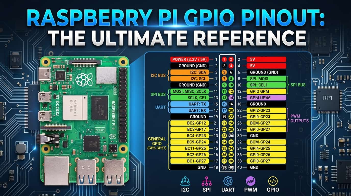
The 40-Pin Layout — What You're Actually Looking At
<!-- IMAGE: Clean labeled GPIO pinout diagram for Raspberry Pi 40-pin header. Show both physical pin numbers (1–40) and GPIO BCM numbers side by side. Color-coded: red for 3.3V, orange for 5V, black for GND, green for GPIO, purple for I2C, blue for SPI, yellow for UART. Alt: "Raspberry Pi 40 pin GPIO pinout diagram labeled" -->The 40 pins break down into these categories:
| Type | Count | What it does |
|---|---|---|
| 3.3V Power | 2 | Powers sensors and logic-level devices |
| 5V Power | 2 | Powers motors, displays, higher-current devices |
| Ground (GND) | 8 | Common ground for all circuits |
| General GPIO | 26 | Programmable input or output pins |
| I2C | 2 | Serial communication (SDA + SCL) |
| SPI | 5 | High-speed serial for displays and ADCs |
| UART | 2 | Serial console and communication |
| PWM | 2 (hardware) | Precise pulse-width modulation |
The Two Numbering Systems — This Is Where Everyone Gets Confused
There are two ways to refer to GPIO pins, and mixing them up is the #1 source of beginner errors.
Physical Pin Numbers (BOARD): Counts from 1 to 40, starting at the corner nearest the SD card slot. Pin 1 is always 3.3V. This is the physical position on the board.
BCM Numbers (Broadcom): The number the Broadcom chip uses internally. GPIO17 in BCM is physical pin 11. These are the numbers you see in most code and most wiring diagrams.
When you write Python code, you choose one system and stick with it for the entire script:
GPIO.setmode(GPIO.BCM)    # Use BCM numbers (GPIO17, GPIO27, etc.)
# OR
GPIO.setmode(GPIO.BOARD)  # Use physical pin numbers (11, 13, etc.)
My advice: use BCM. Every schematic, every tutorial, every datasheet refers to BCM numbers. Learning both causes confusion; BCM is the industry standard.
Voltage Rules — Read This Before Touching Anything
The Raspberry Pi GPIO pins operate at 3.3V logic. This is not negotiable.
- Applying 5V to a GPIO pin will damage your Pi. Unlike Arduino, there is no protection circuitry.
- The 5V pins on the header supply 5V but you cannot use them as GPIO — they are power rails only.
- If you're connecting a 5V device (like an HC-SR04 ultrasonic sensor), you need a voltage divider or level shifter on the signal line coming back into the Pi.
Maximum current per GPIO pin: 16mA. Maximum total current across all GPIO: 50mA. Always use a resistor with LEDs (330Ω–1kΩ for 3.3V).
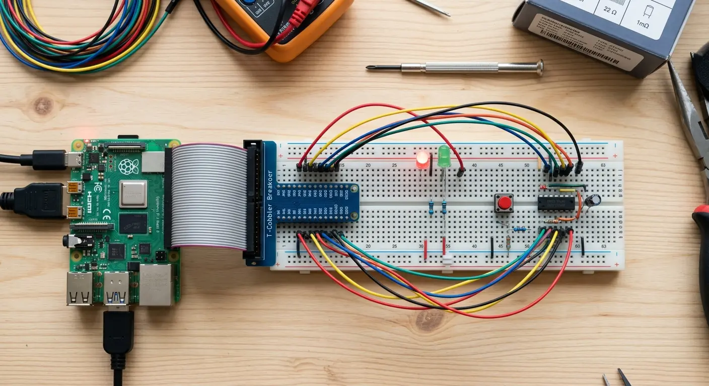
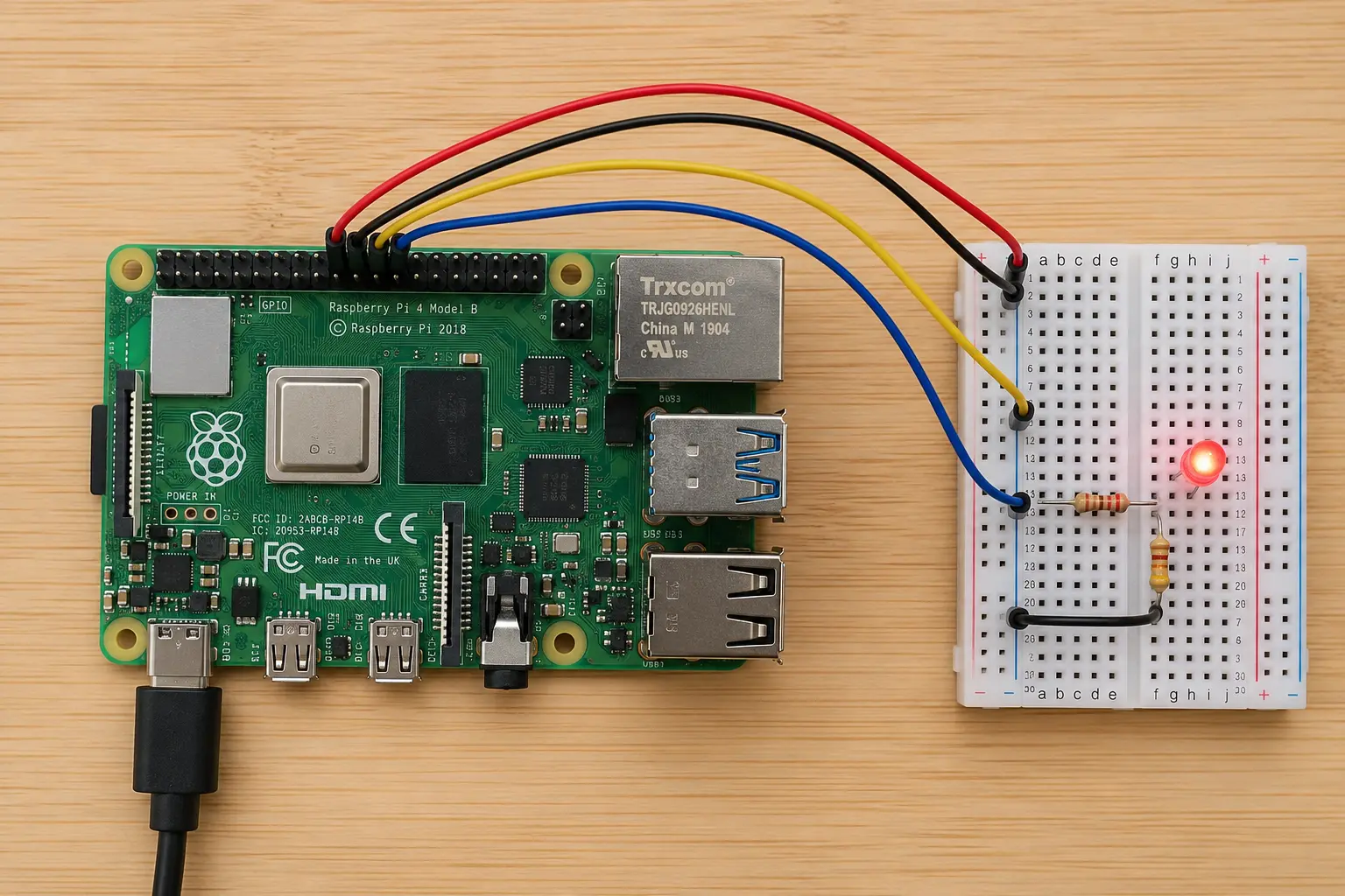
Your First Circuit — Blinking an LED
Let's wire something up before going deeper. You need:
- Raspberry Pi (any 40-pin model)
- 1× LED (any colour)
- 1× 330Ω resistor
- Breadboard + 2 jumper wires
Wiring:
- GPIO17 (physical pin 11) → 330Ω resistor → LED anode (long leg)
- LED cathode (short leg) → GND (physical pin 9)
GPIO.cleanup() in the finally block is not optional. Without it, pins stay in whatever state they were left in when your script crashes, which can cause problems the next time you run anything.
PWM — Making Things Fade and Spin
PWM (Pulse Width Modulation) is how you control brightness, motor speed, and servo position using a digital pin. Instead of being fully on or fully off, the pin rapidly switches between the two — the ratio of on-time to off-time (the duty cycle) determines the effective output.
A duty cycle of 100% = fully on. 50% = half brightness. 0% = off.
The Raspberry Pi has two hardware PWM channels — GPIO12 and GPIO18 (both on physical pins). All other PWM is software-based, which works fine for LEDs but can be jittery for precise servo control.
Fading an LED with PWM
Controlling a Servo with PWM
Servos expect a 50Hz signal. The pulse width between 1ms and 2ms controls the position (0° to 180°).
Tip: Power your servo from the 5V pin (or an external supply), not from GPIO. Servos draw more current than GPIO pins can safely provide. Only the signal wire goes to GPIO18.
I2C — Talking to Sensors and Displays
I2C (Inter-Integrated Circuit) lets you connect multiple devices to just two wires: SDA (data) and SCL (clock). Each device has a unique address, so the Pi knows who it's talking to.
On the Raspberry Pi:
- SDA → GPIO2 (physical pin 3)
- SCL → GPIO3 (physical pin 5)
Enable I2C First
I2C is disabled by default. Enable it:
sudo raspi-config
Go to Interface Options → I2C → Enable → Finish → Reboot.
To verify your device is detected after wiring:
sudo apt install i2c-tools
i2cdetect -y 1
You'll see a grid with your device's address (e.g., 0x76 for BME280, 0x3C for most OLED displays). If the grid is empty, check your wiring.
Reading a BME280 Temperature + Humidity + Pressure Sensor
Install the library:
pip3 install smbus2 bme280
import smbus2
import bme280

port = 1
address = 0x76   # Check with i2cdetect if yours is 0x77

bus = smbus2.SMBus(port)
calibration_params = bme280.load_calibration_params(bus, address)

data = bme280.sample(bus, address, calibration_params)

print(f"Temperature : {data.temperature:.1f} °C")
print(f"Humidity    : {data.humidity:.1f} %")
print(f"Pressure    : {data.pressure:.1f} hPa")
That's it. Three wires (SDA, SCL, GND) plus power, and you have a full weather station reading in under 10 lines of Python.
Reading a Button — GPIO as Input
So far everything has been output. Input works the other way — the Pi reads the state of a pin to detect a button press, a sensor trigger, or any digital signal.
pull_up_down=GPIO.PUD_UP activates the internal pull-up resistor. Without this, a floating pin reads random noise — your button would appear to press itself randomly. Always use pull-up or pull-down on input pins.
Using GPIO Zero — The Cleaner Way
If the RPi.GPIO library feels verbose, GPIO Zero ships with Raspberry Pi OS and wraps everything in a much friendlier API.
from gpiozero import LED, Button
from signal import pause

led    = LED(17)
button = Button(24)

button.when_pressed  = led.on
button.when_released = led.off

pause()   # Keep the script running
That's the same button-controls-LED circuit in 6 lines instead of 20. GPIO Zero handles cleanup automatically, supports PWM, servos, motion sensors, distance sensors, and much more. For most projects it's the better starting point.
Quick Reference — Most Used Pins
| Physical Pin | BCM | Function | Common Use |
|---|---|---|---|
| 1 | — | 3.3V | Power for sensors |
| 2 | — | 5V | Power for motors/displays |
| 3 | GPIO2 | I2C SDA | Sensors, OLEDs |
| 5 | GPIO3 | I2C SCL | Sensors, OLEDs |
| 6 | — | GND | Ground |
| 11 | GPIO17 | GPIO | LED, relay, general |
| 12 | GPIO18 | GPIO / PWM | LED dimming, servo |
| 13 | GPIO27 | GPIO | Button, sensor |
| 19 | GPIO10 | SPI MOSI | Displays, ADCs |
| 21 | GPIO9 | SPI MISO | Displays, ADCs |
| 23 | GPIO11 | SPI SCLK | Displays, ADCs |
| 32 | GPIO12 | Hardware PWM | Servo, audio |
| 35 | GPIO19 | Hardware PWM | Servo, audio |
Common Mistakes (and How to Avoid Them)
Forgetting GPIO.cleanup() — pins stay in their last state. Next script run may behave unexpectedly. Always put it in a finally block.
Using 5V on a GPIO pin — there is no protection. The pin, and potentially the SoC, will be damaged. Double-check every wire before powering on.
Mixing BCM and BOARD numbers in one script — pick one at the start and never switch. If your LED is on GPIO17 BCM but you use GPIO.setup(11, ...) thinking it's the same pin, the wrong pin gets configured.
No pull-up/pull-down on input pins — floating inputs read garbage. Always specify PUD_UP or PUD_DOWN.
Powering servos or motors directly from GPIO — these devices draw more current than GPIO can supply. Use the 5V rail or an external supply with a shared ground.
What to Build Next
You now have a working mental model of the Raspberry Pi GPIO system. Here's where the real fun starts:
- Home automation: Connect a relay module to switch mains appliances, publish state via MQTT to Home Assistant
- Environmental monitor: BME280 (temperature, humidity, pressure) + an OLED display on I2C — two devices, same two wires
- Camera + GPIO: Trigger the Pi Camera with a PIR motion sensor on GPIO to build a wildlife camera
- Motor control: An L298N motor driver on GPIO lets you build a robot chassis with full directional control
The GPIO header is the same across all 40-pin Raspberry Pi models. Everything in this guide works identically on a Pi 3B+, 4B, or 5.
Related guides on SolderHub:
- ESP32 Deep Sleep: Extend Battery Life from Days to Months
- How to Use MQTT with ESP32 and Home Assistant
- ESP32 vs Arduino: Which Should You Choose?
Published on SolderHub — Build. Simulate. Learn.