

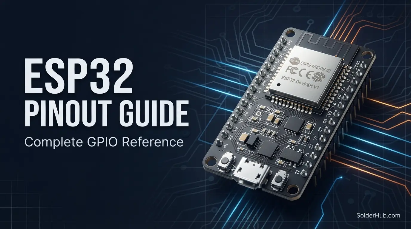
Ask five people what the ESP32 pinout looks like and you'll get five different answers — and here's the frustrating part: they might all be right. Unlike the Uno, where one board means one pin layout forever, "ESP32" is really an umbrella term for a chip that gets soldered onto dozens of different dev board designs, each breaking out a different subset of pins in a different arrangement.
That variety is exactly why so many people end up confused the first time they wire one up. You find a wiring diagram online, it doesn't quite match your board, and suddenly you're not sure if pin 12 is safe to use or if you're about to brick your board on the next power cycle (spoiler: some ESP32 pins really can do that).
Board naming adds another layer of confusion on top of that. Plenty of ESP32 dev boards are sold under names like NodeMCU-32S, which has nothing to do with the original NodeMCU firmware project built for the ESP8266 -- vendors reused a familiar name because the layout resembles the ESP8266 board it followed. Under the silkscreen, a NodeMCU-32S is a standard ESP32-WROOM-32 module on a breakout board, and everything in this guide applies to it exactly as written.
This guide focuses on the layout you'll see on the overwhelming majority of ESP32 dev boards in the wild — the 38-pin WROOM-32 devkit — and walks through what every functional group of pins actually does, including the handful that are genuinely dangerous to get wrong.
Why the ESP32's Pinout Feels Chaotic (and Why It Isn't, Really)
The ESP32 is a dual-core Xtensa LX6 processor running up to 240 MHz, with built-in Wi-Fi and Bluetooth, and — depending on the exact module — anywhere from 30 to 38 physical pins broken out on the dev board. Underneath all that, the actual chip exposes around 34 GPIOs, but not all of them are safe to use freely, and that's the part tutorials often skip past.
Some pins are input-only. Some are wired internally to the board's onboard flash chip and are completely off-limits. A handful control the boot mode and can send your board into a boot loop if you get the wiring wrong at power-on. None of this is arbitrary — it's a side effect of squeezing Wi-Fi, Bluetooth, a dual-core CPU, and SPI flash onto one small chip — but it does mean the ESP32 rewards a bit of upfront pin-reading in a way the Uno never demanded.
Power Pins
| Pin | Description |
|---|---|
| VIN / 5V | Input voltage, typically 5V via USB or the VIN pin depending on board |
| 3V3 | Regulated 3.3V output — this is the board's actual logic level |
| GND | Ground (multiple pins, all connected) |
| EN | Enable pin — pull LOW to reset the chip |
The single most important thing to internalize about the ESP32: every GPIO on this board runs at 3.3V logic, not 5V. This trips up a lot of people coming from the Arduino Uno, where 5V is the norm. Feed a 5V signal into an ESP32 GPIO pin — a 5V sensor output, a level from another 5V board — and you risk damaging the pin or the chip outright. If you're mixing an ESP32 with 5V peripherals, you need a logic level shifter on every signal line, no exceptions.
The EN pin is your hardware reset — pulling it LOW and releasing it restarts the chip, which is exactly what the onboard reset button is wired to do.
GPIO Pins — The General Case
Most GPIOs on the ESP32 can be configured as input or output, with internal pull-up or pull-down resistors available in software:
pinMode(2, OUTPUT);
digitalWrite(2, HIGH);

pinMode(4, INPUT_PULLUP);
That's the easy part. The hard part is knowing which of these "general purpose" pins actually have restrictions, so let's go through them.
Input-Only Pins (34, 35, 36, 39)
GPIOs 34, 35, 36 (often labeled VP), and 39 (often labeled VN) are input-only. They have no internal pull-up or pull-down resistors, and they cannot be configured as outputs under any circumstances — this is a hardware limitation, not a software restriction you can code your way around.
pinMode(34, INPUT);  // fine
pinMode(34, OUTPUT); // will silently fail to behave as expected
These pins are great candidates for analog sensor inputs or simple digital reads where you don't need a pull-up, but if your circuit relies on an internal pull-up resistor (a lot of button and simple sensor wiring does), you'll need an external one on these four pins specifically.
Strapping Pins (0, 2, 4, 5, 12, 15)
These pins are sampled by the ESP32 at the exact moment it boots, and their state determines things like which mode the chip boots into (normal flash boot vs. UART download mode) and the logging baud rate. GPIO0 is the most notorious of these — it's the pin your dev board's "BOOT" button is wired to, and it's why holding BOOT while pressing reset puts the board into flashing mode.
The practical implication: if you're using these pins for your own circuit, make sure whatever you connect doesn't hold them in a state that interferes with boot at power-up. GPIO12 in particular has bitten a lot of people — if it's pulled HIGH at boot, it can select the wrong flash voltage and cause the board to fail to boot entirely. It's usually best to treat pins 0, 2, 12, and 15 as "usable, but only after boot has completed," and avoid connecting anything to them that actively drives a strong signal during power-up.
Pins That Are Simply Off-Limits (6, 7, 8, 9, 10, 11)
GPIOs 6 through 11 are wired internally to the SPI flash chip that stores your firmware. On virtually every ESP32 dev board, these pins aren't even broken out to a header — and if your particular board does expose them, do not use them for anything. Using these pins for your own circuit will interfere with the board reading its own program from flash, and at best your code won't run; at worst you'll need special tools to recover the board.
Analog Input (ADC)
The ESP32 has two separate ADC controllers, and knowing which one you're using matters more than it should.
| ADC | Pins | Wi-Fi Compatible? |
|---|---|---|
| ADC1 | GPIO32, 33, 34, 35, 36, 39 | Yes |
| ADC2 | GPIO0, 2, 4, 12, 13, 14, 15, 25, 26, 27 | No — conflicts with Wi-Fi driver |
int reading = analogRead(34); // 0–4095, 12-bit resolution
This is the single most common ESP32 "gotcha" that catches people out mid-project: ADC2 pins stop working reliably the moment Wi-Fi is active, because the Wi-Fi driver takes priority over the ADC2 hardware internally. Your analog sensor works perfectly in testing, you add WiFi.begin(), and suddenly readings go flaky or return zero. If you need reliable analog input in a Wi-Fi-connected project, stick to ADC1 pins (32–39) and leave ADC2 for non-Wi-Fi builds or digital-only use.
The ADC itself gives 12-bit resolution (0–4095), a step up from the Uno's 10-bit (0–1023), though real-world linearity near the extremes of the voltage range is a known weak point — if you need precision at the very top or bottom of the range, expect to calibrate.
PWM — Not Fixed Pins, a Fixed Peripheral
This is where the ESP32 genuinely differs from the Uno and Mega in a way that surprises people coming from either board: there's no dedicated set of "PWM pins." Instead, the ESP32 has a peripheral called the LEDC (LED Control) driver, and you can assign a PWM channel to almost any GPIO in software.
ledcAttach(2, 5000, 8);   // pin, frequency (Hz), resolution (bits)
ledcWrite(2, 128);        // ~50% duty at 8-bit resolution
There are 16 independent PWM channels available (organized across two timer groups), and you assign them to pins yourself rather than looking for a tilde on the silkscreen. This is more flexible than the Uno's fixed six PWM pins, but it also means you can't just glance at the board to know what's PWM-capable — nearly everything is, except the input-only and flash pins already covered above.
Touch-Sensitive Pins
Ten GPIOs double as capacitive touch inputs, useful for touch buttons without any extra hardware:
| Touch Channel | GPIO |
|---|---|
| T0 | 4 |
| T1 | 0 |
| T2 | 2 |
| T3 | 15 |
| T4 | 13 |
| T5 | 12 |
| T6 | 14 |
| T7 | 27 |
| T8 | 33 |
| T9 | 32 |
int touchValue = touchRead(T0);
Notice several of these overlap with the strapping pins covered earlier (0, 2, 12, 15) — one more reason to be deliberate about which "extra" pins you lean on for touch input versus which you reserve for safer, unrestricted GPIOs.
I2C
The ESP32's default I2C pins, though — unlike the Uno — these are fully reassignable in software to almost any GPIO:
| Pin | Function |
|---|---|
| GPIO21 | SDA (default) |
| GPIO22 | SCL (default) |
#include <Wire.h>
Wire.begin();               // uses default pins 21/22
Wire.begin(4, 5);           // or specify your own SDA/SCL pins
This flexibility is genuinely useful when your board layout or enclosure makes the default pins awkward to route, but it also means you need to double-check which pins a given library or example sketch expects — "the I2C pins" isn't a fixed physical fact on the ESP32 the way it is on the Uno.
SPI
The ESP32 has two usable SPI buses in the Arduino framework, VSPI and HSPI, each with their own default pin set:
| Bus | MOSI | MISO | SCK | CS |
|---|---|---|---|---|
| VSPI | 23 | 19 | 18 | 5 |
| HSPI | 13 | 12 | 14 | 15 |
#include <SPI.h>
SPI.begin();  // defaults to VSPI on most boards
Like I2C, these pins can be remapped in software if needed, but the defaults above match what you'll find on almost every WROOM-32 devkit and are the safest starting point for a new project.
UART — Three Serial Ports This Time
Unlike the Uno's single UART, the ESP32 gives you three, though one of them is already spoken for.
| Port | TX | RX | Typical Use |
|---|---|---|---|
| UART0 | GPIO1 | GPIO3 | USB / Serial Monitor (programming) |
| UART1 | GPIO10 | GPIO9 | Rarely used — pins overlap with flash |
| UART2 | GPIO17 | GPIO16 | Free for your own peripheral |
Serial2.begin(9600, SERIAL_8N1, 16, 17);
UART2 is your practical second serial port for GPS modules, other microcontrollers, or Bluetooth-adjacent hardware — UART1's default pins overlap with the flash-connected GPIOs discussed earlier, so it's rarely usable without remapping to different pins first.
RTC GPIOs and Deep Sleep Wake-Up
One of the ESP32's headline features is deep sleep, where the chip draws only microamps of current, and a specific subset of pins — the RTC GPIOs — can wake it back up:
esp_sleep_enable_ext0_wakeup(GPIO_NUM_33, 1);  // wake on GPIO33 going HIGH
esp_deep_sleep_start();
The RTC-capable pins are GPIO0, 2, 4, 12–15, 25–27, and 32–39 — conveniently, this overlaps heavily with the ADC1 and ADC2 pin sets, since they all live on the same low-power RTC domain of the chip. If you're building a battery-powered sensor that wakes on a button press or a PIR trigger, this is the pin list to design around.
Practical Pin Usage Tips
Default to ADC1 for anything that needs to coexist with Wi-Fi. This single decision prevents the most common "my sensor stopped working after I added networking" bug in ESP32 projects.
Treat GPIO0, 2, 5, 12, and 15 with extra care during circuit design, not because they're unusable, but because whatever you attach to them needs to not interfere with the chip's boot sequence. A pull-down resistor on a relay module, for instance, can be enough to prevent GPIO12 from booting correctly if wired without thought.
Use a level shifter for any 5V peripheral, always. This isn't optional the way it sometimes is with the Uno's more tolerant digital pins — ESP32 GPIOs are not 5V tolerant, and this is the single fastest way people damage a brand-new board.
Pick your I2C and SPI pins deliberately and document them, since — unlike the Uno — there's no universal default that every example sketch assumes. Future you (or anyone reading your code) will thank you for a comment listing which physical pins map to which bus.
Don't assume your dev board breaks out every GPIO. Some compact ESP32 boards skip GPIO6–11 entirely (correctly, since they're reserved) but also omit a few of the input-only or strapping pins to simplify the header layout. Check your specific board's printed silkscreen or datasheet before assuming a pin from a generic ESP32 diagram is physically present.
Common Mistakes and How to Avoid Them
Wiring a 5V sensor straight into a GPIO. The most frequent way people damage an ESP32. Always shift 5V logic down to 3.3V first.
Expecting ADC2 to work once Wi-Fi is running. It won't, reliably. Move analog sensors to ADC1 pins before you add networking code, not after you've already debugged why the readings went strange.
Using GPIO6–11 because a diagram showed them as "available." These are internally wired to flash. If your board exposes them at all, leave them alone entirely.
Assuming a pull-up resistor exists on GPIO34–39. These four input-only pins have no internal pull-up or pull-down. If your circuit needs one, add it externally.
Powering the board's 3.3V rail with heavy external loads. The onboard regulator on most dev boards can supply a few hundred milliamps at most. Driving several servos or a bright LED strip off the 3V3 pin will brown out the chip — give hungry peripherals their own supply.
Summary: ESP32 Pin Reference at a Glance
| Feature | Detail |
|---|---|
| Total GPIOs (typical devkit) | ~34, with several restricted |
| Input-only pins | 34, 35, 36, 39 |
| Flash-reserved (avoid) | 6, 7, 8, 9, 10, 11 |
| Strapping pins (boot-sensitive) | 0, 2, 4, 5, 12, 15 |
| ADC1 (Wi-Fi safe) | 32, 33, 34, 35, 36, 39 |
| ADC2 (not Wi-Fi safe) | 0, 2, 4, 12–15, 25–27 |
| PWM | Any usable GPIO, via LEDC (16 channels) |
| Touch inputs | 10 channels (T0–T9) |
| Default I2C | SDA 21, SCL 22 (reassignable) |
| Default SPI (VSPI) | MOSI 23, MISO 19, SCK 18, CS 5 |
| UART | 3 ports — UART0 (USB), UART2 free by default |
| Logic level | 3.3V only — not 5V tolerant |
The ESP32's pinout has a reputation for being confusing, but it's really just a chip with a lot of internal jobs — flash storage, boot mode selection, Wi-Fi, deep sleep wake logic — all sharing the same limited set of physical pins. Once you know which pins carry those extra responsibilities and which are genuinely free to use however you like, the board stops feeling like a minefield and starts feeling like what it actually is: one of the most capable, flexible microcontrollers you can buy for a few dollars.
ESP32 WROOM-32 · Dual-Core Xtensa LX6 · Wi-Fi + Bluetooth · ~34 GPIO · 2x ADC · 3x UART · SPI · I2C · PWM (LEDC)
Quick Answers to Common ESP32 Pin Questions
How many usable GPIO pins does the ESP32 actually have? Around 34 physically exist on the chip, but factor in the 6 flash-reserved pins you should never touch and the 4 input-only pins with special handling, and you're realistically working with roughly 22–25 fully flexible general-purpose pins on a typical devkit.
Why does my sensor stop working when I connect to Wi-Fi? Almost certainly because it's wired to an ADC2 pin. ADC2 shares hardware with the Wi-Fi radio and becomes unreliable the moment Wi-Fi is active. Move the sensor to an ADC1 pin (32, 33, 34, 35, 36, or 39).
Which pins are safe to use without reading a datasheet first? As a rough rule of thumb: GPIO16–19, 21–23, and 25–27 are generally safe, flexible, general-purpose choices on most WROOM-32 devkits, with none of the boot-sensitivity or flash-reservation issues of the other groups.
Can I use 5V sensors with the ESP32? Only through a logic level shifter. The ESP32 is a 3.3V device throughout, and its GPIOs are not rated to tolerate 5V signals the way some other 3.3V boards' pins are.
What's the difference between GPIO34 and a regular GPIO like GPIO4? GPIO34 (and 35, 36, 39) are input-only at the hardware level — they physically cannot drive an output signal and have no internal pull-up/pull-down circuitry, whereas GPIO4 can be freely configured as input or output with internal pull resistors available.
Do all ESP32 boards have the same pinout? No — this is the biggest source of confusion with this chip. The underlying silicon is consistent, but different board manufacturers break out different pin subsets, use different silkscreen labels, and sometimes wire onboard peripherals (like an OLED display or camera) directly onto GPIOs that would otherwise be free. Always check your specific board's diagram, treating this guide as the reference for the chip's capabilities rather than a guaranteed match to every board's silkscreen.
Where to Go From Here
Once the restricted pins and dual-ADC quirks stop being a surprise, the ESP32 turns into one of the most flexible boards available at its price point — a genuinely different category of project becomes possible compared to an Uno or even a Mega, purely because of the built-in networking. The natural next step from here is usually wiring up a first Wi-Fi-connected sensor project, at which point the ADC1-vs-ADC2 distinction covered above stops being trivia and starts being the thing that determines whether your project works on the first try or sends you searching forums for why your readings went to zero the moment you called WiFi.begin().