

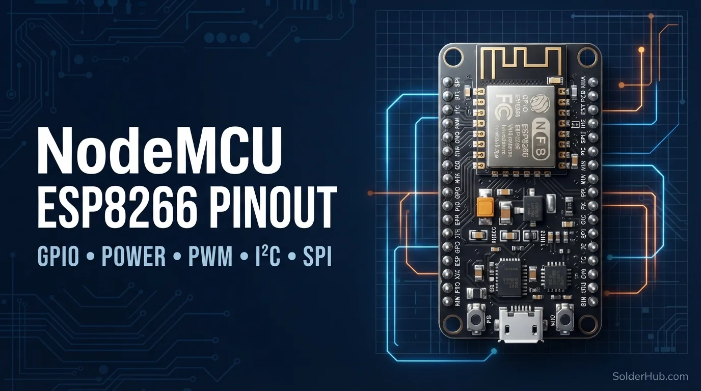
If you've ever wired up a NodeMCU, written pinMode(5, OUTPUT), and then spent twenty minutes wondering why your LED is blinking on the completely wrong pin — welcome. Every single ESP8266 NodeMCU user hits this exact wall, usually late at night, usually on a project that "should only take five minutes."
Here's the thing nobody tells you up front: the numbers printed on your NodeMCU board (D0, D1, D2...) are not the actual GPIO numbers the chip uses internally. They're two completely different numbering systems living on the same 30 pins, and depending on which library or which line of code you're looking at, you might be dealing with either one. Once you see why this happened and memorize the mapping, it stops being confusing — but until then, it's the single most common source of "why doesn't my code work" bugs on this board.
Let's untangle it properly.
Why Two Numbering Systems Exist in the First Place
The ESP8266 is a bare chip. Espressif designed it with GPIO pins numbered GPIO0 through GPIO16 (with a few gaps — more on that later). That's the chip's native numbering, and it's what the actual silicon datasheet refers to.
NodeMCU, the dev board, wraps that chip in a breadboard-friendly package and — for reasons that made sense to whoever laid out the silkscreen back in the day — relabeled the pins D0 through D8 in a much more "friendly" but completely non-sequential order relative to the GPIO numbers. D0 is GPIO16. D1 is GPIO5. D2 is GPIO4. There's no pattern you can guess your way through.
Then the Arduino core for ESP8266 added a translation layer: constants like D0, D1, D2 are #defined to map automatically to the correct GPIO number. So pinMode(D1, OUTPUT) correctly toggles GPIO5. But pinMode(5, OUTPUT) also compiles fine — except now you're addressing GPIO5 directly, which happens to also be D1, so in that one case it accidentally works. Try pinMode(1, OUTPUT) though, thinking you're targeting D1, and you've actually just grabbed GPIO1 — which is your board's TX pin, shared with the USB serial monitor. That's the trap.
Moral of the story: always use the D constants (D0, D1, D2...) in your code, never the bare number. It removes the ambiguity entirely.
Full Pinout Table
Here's the complete mapping. Bookmark this one.
| Silkscreen Label | GPIO Number | Notes |
|---|---|---|
| D0 | GPIO16 | No PWM, no interrupts, no I2C support. Used for deep sleep wake-up. |
| D1 | GPIO5 | Default I2C SCL. General purpose, safe to use. |
| D2 | GPIO4 | Default I2C SDA. General purpose, safe to use. |
| D3 | GPIO0 | Boot mode pin. Must be HIGH at boot. Has an onboard pull-up. |
| D4 | GPIO2 | Boot mode pin. Must be HIGH at boot. Also drives the onboard blue LED (active LOW). |
| D5 | GPIO14 | Hardware SPI (SCLK). General purpose otherwise. |
| D6 | GPIO12 | Hardware SPI (MISO). General purpose otherwise. |
| D7 | GPIO13 | Hardware SPI (MOSI). General purpose otherwise. |
| D8 | GPIO15 | Boot mode pin. Must be LOW at boot. Hardware SPI (CS). |
| A0 | ADC0 | Single analog input, 0–3.3V on most NodeMCU boards via onboard divider. |
| RX | GPIO3 | Hardware UART RX. Shared with USB serial monitor. |
| TX | GPIO1 | Hardware UART TX. Shared with USB serial monitor. |
| SD2, SD3, CLK, CMD, SD0, SD1 | GPIO9, 10, 6, 11, 7, 8 | Connected internally to the SPI flash chip. Not usable, not broken out on most boards. |
That last row trips people up occasionally — if you've ever wondered why NodeMCU only gives you 9 usable GPIOs instead of the ESP8266's full 17, that's why. Six of them are permanently busy talking to the onboard flash memory and were never brought out to a pin header.
Power Pins
| Pin | Description |
|---|---|
| VIN | 5V input (via USB or external supply) |
| 3V3 | Regulated 3.3V output/rail — this is the chip's native operating voltage |
| GND | Ground (multiple pins, all connected) |
| EN / RST | Pull LOW to reset the chip; also has an onboard reset button on most boards |
The critical thing to burn into memory here, especially if you're coming from Arduino Uno or Mega like most people are: the ESP8266 is a 3.3V device and none of its GPIO pins are 5V tolerant. Not even a little bit. On an Uno you can get away with a 5V sensor output going into a digital pin most of the time. Do that here and you risk quietly cooking the pin, or the whole chip, over time. If you're feeding it a signal from a 5V sensor (plenty of cheap IR sensors and ultrasonic modules are 5V), put a voltage divider or a proper logic level shifter in between. Don't skip this step because "it worked once on the breadboard."
Digital I/O — Which Pins You Can Actually Use Freely
Out of the 9 broken-out GPIOs, only five are what I'd call genuinely "use it for anything" pins: D1, D2, D5, D6, D7. The rest all come with an asterisk.
pinMode(D1, OUTPUT);
digitalWrite(D1, HIGH);
D0 (GPIO16) is the odd one out — it's on a completely separate part of the chip from the rest of the GPIOs, which is why it can't do PWM, can't trigger interrupts, and can't do I2C. Its one special talent is waking the chip from deep sleep, which makes it genuinely useful for battery-powered projects, just not as a general-purpose pin.
D3, D4, and D8 are the ones that will bite you if you don't know about them upfront — covered in detail below, because it deserves its own section.
Boot Mode Pins — Read This Before You Wire Anything to D3, D4, or D8
This is the section that saves you the most debugging time, so don't skip it.
When the ESP8266 powers on or resets, it briefly checks the logic level on three specific pins to decide how to boot — whether to run your uploaded program normally, or drop into flashing mode. Those three pins are:
- D3 (GPIO0) — must read HIGH at boot to run normally. Pull it LOW at boot and the chip enters flash/programming mode instead of running your code.
- D4 (GPIO2) — must also read HIGH at boot.
- D8 (GPIO15) — must read LOW at boot. This one's the opposite of the other two, and it's the one people forget most often.
Here's where it actually causes problems in real projects: say you wire a relay module or an LED driver to D8, and that module's default state happens to pull the pin HIGH when the board is unpowered (a lot of relay boards do this through their pull-up resistors). Power on the NodeMCU, and it fails to boot at all — no blink, no serial output, nothing. It's not a bricked board, it's just stuck refusing to start because D8 wasn't LOW at the moment of boot. Swap that connection to D1, D2, D5, D6, or D7 instead, and the exact same relay module works perfectly.
Same logic in reverse for D3 and D4 — if something is actively pulling either of those LOW during boot (a button wired without a proper pull-up resistor is the classic culprit), the board boots into flash mode and just sits there looking dead.
Practical rule: treat D3, D4, and D8 as pins you use last, only for things that don't interfere with their power-on state — buttons with proper pull-ups, or outputs that default to the right level. For anything else, reach for D1, D2, D5, D6, or D7 first.
One more quirk worth knowing: D4 doubles as the onboard blue LED, and it's wired active-LOW, meaning digitalWrite(D4, LOW) turns the LED on. If you're using D4 for something else and you see the onboard LED flickering along with your signal, that's expected — it's the same physical pin.
PWM Pins
Every usable GPIO on the ESP8266 can do PWM — D0 is the only exception. That's actually more flexible than the Uno in terms of pin coverage, but there's a catch: it's software PWM, generated by the core toggling the pin rapidly rather than dedicated PWM hardware like the ATmega chips have. The default frequency is around 1 kHz, and if you're driving multiple PWM pins at once while also doing WiFi work, you can occasionally see slight jitter.
analogWrite(D5, 512); // range is 0–1023, not 0–255 like classic Arduino
Worth noting for anyone used to the classic 0–255 range on Uno/Mega: ESP8266's analogWrite() defaults to a 10-bit range (0–1023). It's an easy one-line bug to introduce if you copy-paste PWM code from an old Uno sketch without adjusting the scale.
Analog Input (A0)
You get exactly one analog input pin, and that's a real step down if you're used to the Mega's sixteen. The raw ESP8266 chip's ADC only accepts 0–1.0V, which would be useless for most sensors — so NodeMCU boards add an onboard resistor divider that extends the usable range to roughly 0–3.3V. That's why A0 behaves fine with a 3.3V-referenced sensor but you should still never feed it a raw 5V signal.
int raw = analogRead(A0);
float voltage = raw * (3.3 / 1023.0);
Because there's only one analog pin, any project reading multiple analog sensors (soil moisture and an LDR at the same time, say) needs either an analog multiplexer chip or a switch to a board with more ADC channels. This is one of the more common walls people hit moving from Uno to NodeMCU — plan for it before you start wiring.
I2C — D1 and D2 by Convention, Not by Hardware
The ESP8266 doesn't have a dedicated I2C hardware peripheral. What you're using is a bit-banged (software-driven) I2C implementation in the Arduino core. By default, Wire.begin() uses D1 as SCL and D2 as SDA, but unlike a chip with genuine hardware I2C, you can actually reassign these to almost any other usable GPIO:
#include <Wire.h>
Wire.begin(D2, D1);  // SDA, SCL — note the order
Wire.begin(D6, D5);  // or remap to any other free pins
Notice the argument order is SDA first, then SCL — reversed from what you'd expect if you're used to seeing SCL listed first on a datasheet. Getting this backwards is a quiet, annoying bug: the bus just doesn't respond, and there's no error message telling you why.
As always with I2C, you need pull-up resistors on both lines (4.7kΩ is the standard). Most breakout boards — OLEDs, BME280s, RTC modules — already include them, so you usually don't need to add your own.
SPI — Hardware, on D5 Through D8
Unlike I2C, SPI on the ESP8266 is real hardware, and it lives on a fixed set of pins:
| Pin | Function |
|---|---|
| D5 (GPIO14) | SCLK (Clock) |
| D6 (GPIO12) | MISO (Master In, Slave Out) |
| D7 (GPIO13) | MOSI (Master Out, Slave In) |
| D8 (GPIO15) | CS / SS (Chip Select) |
#include <SPI.h>
SPI.begin();
This is exactly why D8 is both your SPI chip-select pin and one of the boot-mode pins mentioned earlier — if you're driving an SD card or a display over hardware SPI, keep in mind that whatever's connected to D8 needs to allow the pin to sit LOW at power-on, or your board simply won't start.
UART (Serial)
The ESP8266 has exactly one hardware UART, on RX (GPIO3) and TX (GPIO1) — the same pins used by the USB-to-serial chip for uploading code and for the Serial Monitor. That's a real limitation if you're coming from the Mega's four independent hardware serial ports: there's no Serial1, Serial2, Serial3 equivalent here.
If your project needs to talk to a second serial device (a GPS module, for instance) and keep the USB serial connection free for debugging, your only real option is SoftwareSerial on a spare pin pair — with the caveat that it's noticeably less reliable at higher baud rates and can stumble if WiFi activity interrupts the timing.
#include <SoftwareSerial.h>
SoftwareSerial mySerial(D6, D7); // RX, TX
mySerial.begin(9600);
Common Mistakes and How to Avoid Them
Wiring something to D8 without checking its default state. This is, by a wide margin, the number one cause of "my NodeMCU won't even turn on" posts. If the board doesn't boot, disconnect whatever's on D8 first before assuming the hardware is dead.
Assuming 5V tolerance because you're used to Arduino. The ESP8266 is not the Uno. Every GPIO expects 3.3V logic. A 5V signal on a data pin, even briefly, is bad news — always level-shift.
Using pinMode(5, ...) instead of pinMode(D1, ...). They happen to point at the same physical pin, which makes this bug sneaky — until you try the same trick with a pin number that doesn't line up, and suddenly nothing works and you don't know why.
Trying to use two hardware UARTs like on the Mega. There's only one here. Plan your project around that limit, or budget for SoftwareSerial's quirks.
Forgetting D0 can't do PWM or interrupts. It's easy to grab D0 out of habit for a general-purpose task, since it's first in the list, and then wonder why attachInterrupt() silently refuses to behave.
NodeMCU ESP8266 vs Arduino Uno vs Mega — At a Glance
| Feature | Uno | Mega 2560 | NodeMCU ESP8266 |
|---|---|---|---|
| Logic Level | 5V | 5V | 3.3V (not 5V tolerant) |
| Usable Digital I/O | 14 | 54 | 9 |
| Analog Inputs | 6 | 16 | 1 |
| Hardware UARTs | 1 | 4 | 1 |
| PWM Type | Hardware | Hardware | Software |
| Built-in WiFi | No | No | Yes |
| Boot-sensitive pins | None | None | 3 (D3, D4, D8) |
The trade-off is obvious once you see it laid out: you're giving up a lot of pins and losing 5V tolerance, but you're gaining WiFi built directly into the chip, which is the entire reason this board exists. For anything that needs to talk to the internet, send data to Home Assistant, or run without a wired connection, those nine pins go a lot further than they look like they should.
Print the mapping table above, tape it next to your desk, and the D-pin-vs-GPIO confusion stops being a recurring bug and starts being a one-time thing you glance at and move on from.
NodeMCU ESP8266 · ESP8266 (Tensilica L106) · 9 Usable GPIOs · 1 Analog Input · Hardware SPI · Software I2C · Built-in WiFi
Quick Answers to Common NodeMCU Pin Questions
Why does D1 in my code not match GPIO1 on the datasheet? Because they're two different numbering systems for the same physical pins. D1 is GPIO5, not GPIO1 — the D-pin labels printed on the board don't follow the chip's own GPIO numbers in order, so they have to be looked up rather than guessed.
Can I use any GPIO for anything? No — D3, D4, D8, and D0 all carry boot-time or hardware restrictions. Stick to D1, D2, D5, D6, and D7 for general-purpose sensors, buttons, and outputs with no strings attached.
Is the onboard LED active-high or active-low? Active-low on most boards — LOW turns it on, HIGH turns it off, the opposite of what most people expect from a first LED-blink sketch.
Does the NodeMCU have more than one analog pin? No — A0 is the only ADC input. If a project needs to read more than one analog signal, that means an external ADC or a multiplexer.
Why won't my board wake up from deep sleep? D0 needs to be wired directly to RST for the chip to wake itself back up. Without that one connection, deep sleep mode puts the board to sleep permanently.
Where to Go From Here
Once the D-pin-to-GPIO mapping and the D3/D4/D8 boot restrictions stop causing surprises, wiring D0 to RST for deep sleep is the next thing worth trying on any battery-powered project — it's the one physical connection that unlocks the board's biggest power-saving feature. From there, the same pin logic and boot-mode rules carry over directly to a Wemos D1 Mini, so moving between the two boards for space or pin-count reasons doesn't mean relearning anything.