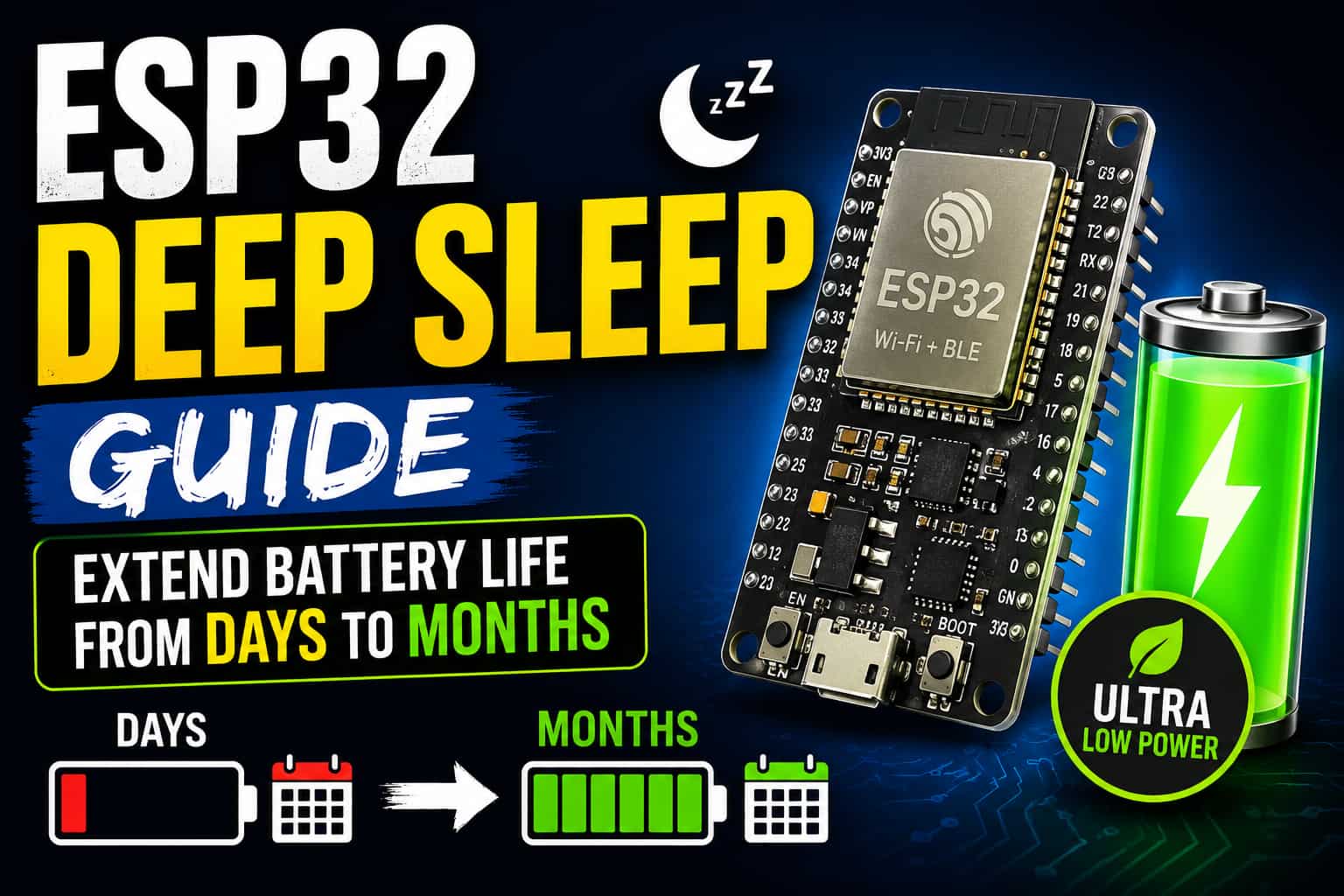
ESP32 Deep Sleep: How I Got My Sensor Node to Last 4 Months on One Battery
I killed a lot of 18650 cells before I figured this out.
My first ESP32 weather station was plugged into a USB power bank. It worked great on my desk. Then I tried to deploy it in my backyard — no outlet, just a fully charged 2500 mAh battery. It was dead in 18 hours.
The ESP32 with Wi-Fi active pulls 80–240 mA. Do the math: 2500 mAh ÷ 150 mA average = about 16 hours. I was basically running a space heater in a plastic box.
The fix wasn't hardware. It was deep sleep.
After adding deep sleep properly, the same battery lasted 4 months. Same ESP32, same sensor, same battery. The only thing that changed was the firmware.
This guide is everything I wish I'd known before I wasted those cells.
What's Actually Happening Inside the Chip
Before touching any code, you need to understand why deep sleep works — otherwise you'll spend hours confused about why variables vanish between wakeups.
The ESP32 isn't one thing. It's a collection of power domains that can be turned off independently:
<!-- IMAGE PLACEHOLDER: ESP32 power domains diagram — showing which blocks stay on during deep sleep -->| Power Domain | Active | Deep Sleep |
|---|---|---|
| Main CPU (both cores) | ✅ Running | ❌ Off |
| Wi-Fi / Bluetooth radio | ✅ Running | ❌ Off |
| Main RAM (520KB SRAM) | ✅ On | ❌ Cleared |
| RTC Controller | ✅ On | ✅ On |
| RTC Memory (8KB) | ✅ On | ✅ On |
| ULP Co-processor | ✅ On | ✅ Optional |
That RTC memory row is the one that matters most. 8KB of memory that survives deep sleep. That's your data lifeline across sleep cycles — boot counts, last sensor readings, Wi-Fi credentials, calibration values, anything you need to remember.
Everything else gets wiped. Including your int count = 0 in setup(). Gone.
The other thing that catches everyone off guard: the ESP32 doesn't pause when it sleeps. It reboots. When the wakeup trigger fires, your setup() runs from the top again. There's no "resuming." It's a full cold boot, just very fast.
This is the mental model shift that makes everything else click:
Deep sleep = scheduled reboot, not a pause
Once you internalize that, the code patterns make total sense.
The 8KB That Saves You: RTC Memory
Before I show any wakeup code, let's talk about RTC_DATA_ATTR. This is the thing I missed for way too long.
RTC_DATA_ATTR int bootCount = 0;
RTC_DATA_ATTR float lastTemperature = 0.0;
RTC_DATA_ATTR bool calibrationDone = false;
Slap RTC_DATA_ATTR in front of any global variable and it lives in RTC memory. It survives every sleep cycle. It only resets on a full power-off or hard reset (the EN button).
A few gotchas I've hit:
Don't use String class in RTC memory. It technically compiles but behaves strangely across reboots. Use char[] arrays instead.
// This will cause weird bugs
RTC_DATA_ATTR String deviceName = "sensor-01"; // ❌

// This works fine
RTC_DATA_ATTR char deviceName[32] = "sensor-01"; // ✅
Initialize on first boot. RTC variables hold garbage values the very first time you power on. Add a flag:
RTC_DATA_ATTR bool firstBoot = true;
RTC_DATA_ATTR float calibration = 0.0;

void setup() {
  if (firstBoot) {
    calibration = 25.0;
    firstBoot = false;
  }
}
You've got 8KB total — some of it is used by the system, so in practice you have about 4–6KB. More than enough for most projects, but don't try to cache a JSON blob in there.
Wakeup Source 1: Timer (The One You'll Use Most)
Set a duration, go to sleep, wake up after that time. This is the foundation of 90% of battery-powered sensor projects.
#include <Arduino.h>

#define SLEEP_SECONDS 30

RTC_DATA_ATTR int readingNumber = 0;

void setup() {
  Serial.begin(115200);
  delay(100);

  readingNumber++;
  Serial.printf("--- Reading #%d ---\n", readingNumber);

  // Figure out why we woke up
  esp_sleep_wakeup_cause_t cause = esp_sleep_get_wakeup_cause();
  if (cause == ESP_SLEEP_WAKEUP_TIMER) {
    Serial.println("Timer wakeup — taking a reading");
  } else {
    Serial.println("First boot or manual reset");
  }

  // Your sensor code goes here
  // float temp = readSensor();
  // sendToServer(temp);

  Serial.println("Going back to sleep...");
  Serial.flush(); // Don't skip this — lets the UART finish before sleeping

  esp_sleep_enable_timer_wakeup((uint64_t)SLEEP_SECONDS * 1000000ULL);
  esp_deep_sleep_start();
}

void loop() {
  // This never runs in a deep sleep design
}
That 1000000ULL trips up a lot of people. The function takes microseconds, and the ULL suffix prevents integer overflow when you multiply by large numbers. Without it, 30 seconds becomes a garbage value and your device sleeps for a random duration.
Also notice Serial.flush() before sleeping. Without it, the last few characters of your log output get cut off mid-transmission. Small thing, annoying to debug.
Wakeup Source 2: GPIO Pin (ext0)
Sometimes you don't want a fixed timer — you want to sleep until something happens. A button press, a PIR sensor triggering, a door contact opening.
That's ext0. One pin, one event.
<!-- IMAGE PLACEHOLDER: Wiring diagram — push button connected to GPIO 33 with 10k pull-up resistor and ESP32 DevKit -->#include <Arduino.h>
#define WAKEUP_PIN GPIO_NUM_33
RTC_DATA_ATTR int buttonPresses = 0;
void setup() {
Serial.begin(115200);
delay(100);
esp_sleep_wakeup_cause_t cause = esp_sleep_get_wakeup_cause();
if (cause == ESP_SLEEP_WAKEUP_EXT0) {
buttonPresses++;
Serial.printf("Button pressed! Total presses: %d\n", buttonPresses);
// Handle the event — log it, send a notification, whatever
}
// Wake when GPIO 33 goes LOW (button pulls it to GND)
esp_sleep_enable_ext0_wakeup(WAKEUP_PIN, 0);
Serial.println("Waiting for button...");
Serial.flush();
esp_deep_sleep_start();
}
void loop() {}
The catch: ext0 only works with RTC-capable GPIO pins. On the ESP32 WROOM-32, those are: GPIO 0, 2, 4, 12–15, 25–27, 32–39. Try to use GPIO 5 or GPIO 22 and nothing will happen — no error, just silence. I spent an embarrassing amount of time on this.
Wakeup Source 3: Multiple GPIO Pins (ext1)
Same idea as ext0, but you can monitor several pins at once. Useful for multi-button remotes, alarm systems, or anything with more than one trigger.
#include <Arduino.h>

// Monitor GPIO 32 AND GPIO 33
// Bitmask: set bit N to monitor GPIO N
#define WAKE_PINS ((1ULL << GPIO_NUM_32) | (1ULL << GPIO_NUM_33))

void setup() {
  Serial.begin(115200);
  delay(100);

  esp_sleep_wakeup_cause_t cause = esp_sleep_get_wakeup_cause();

  if (cause == ESP_SLEEP_WAKEUP_EXT1) {
    uint64_t triggered = esp_sleep_get_ext1_wakeup_status();

    if (triggered & (1ULL << GPIO_NUM_32)) {
      Serial.println("GPIO 32 triggered — button A");
    }
    if (triggered & (1ULL << GPIO_NUM_33)) {
      Serial.println("GPIO 33 triggered — button B");
    }
  }

  // Wake when ANY of the monitored pins goes HIGH
  esp_sleep_enable_ext1_wakeup(WAKE_PINS, ESP_EXT1_WAKEUP_ANY_HIGH);

  Serial.flush();
  esp_deep_sleep_start();
}

void loop() {}
The bitmask syntax looks ugly but it's straightforward: shift 1 left by the GPIO number, OR them together for multiple pins.
Wakeup Source 4: Touchpad
The ESP32 has 10 capacitive touch pins (T0–T9). You can use a bare wire, a copper pad, or a piece of foil as a touch sensor — and wake from deep sleep when someone touches it.
#include <Arduino.h>

void dummyCallback() {}  // Required but unused

void setup() {
  Serial.begin(115200);
  delay(100);

  esp_sleep_wakeup_cause_t cause = esp_sleep_get_wakeup_cause();

  if (cause == ESP_SLEEP_WAKEUP_TOUCHPAD) {
    touch_pad_t pad = esp_sleep_get_touchpad_wakeup_status();
    Serial.printf("Touch wakeup on pad T%d\n", pad);
  }

  // T0 = GPIO 4. Threshold 40 = sensitivity (lower = more sensitive)
  touchAttachInterrupt(T0, dummyCallback, 40);
  esp_sleep_enable_touchpad_wakeup();

  Serial.println("Touch GPIO 4 to wake...");
  Serial.flush();
  esp_deep_sleep_start();
}

void loop() {}
You'll need to tune the threshold (40 in the example above) for your setup. Touch the pin while monitoring touchRead(T0) in a non-sleep sketch to find your baseline, then set the threshold slightly below that.
A Real Project: Soil Moisture Sensor That Texts You
Here's how all of this comes together in something actually useful — a soil moisture monitor that sleeps most of the day, wakes up every hour, and sends a push notification if the plant needs water.
<!-- IMAGE PLACEHOLDER: Complete wiring — ESP32 + capacitive soil moisture sensor + 18650 battery holder + MOSFET for sensor power control -->#include <Arduino.h>
#include <WiFi.h>
#include <HTTPClient.h>
#define MOISTURE_PIN 34 // ADC pin (input only)
#define SENSOR_POWER 26 // Controls a MOSFET that powers the sensor
#define SLEEP_HOURS 1 // Wake every hour
#define DRY_THRESHOLD 2800 // Raw ADC — above this means "dry"
const char* ssid = "YOUR_SSID";
const char* password = "YOUR_PASSWORD";
const char* ntfyTopic = "https://ntfy.sh/my-plant-alerts"; // ntfy.sh is free
RTC_DATA_ATTR int totalChecks = 0;
RTC_DATA_ATTR int alertsSent = 0;
void sendAlert(int moisture) {
WiFi.begin(ssid, password);
int tries = 0;
while (WiFi.status() != WL_CONNECTED && tries < 20) {
delay(500);
tries++;
}
if (WiFi.status() != WL_CONNECTED) return;
HTTPClient http;
http.begin(ntfyTopic);
http.addHeader("Title", "Plant Alert");
http.addHeader("Priority", "high");
String msg = "Moisture reading: " + String(moisture) + " — time to water!";
http.POST(msg);
http.end();
WiFi.disconnect(true);
WiFi.mode(WIFI_OFF);
}
void setup() {
Serial.begin(115200);
totalChecks++;
// Power on the sensor
pinMode(SENSOR_POWER, OUTPUT);
digitalWrite(SENSOR_POWER, HIGH);
delay(100); // Let it stabilize
int moisture = analogRead(MOISTURE_PIN);
Serial.printf("Check #%d — Moisture: %d\n", totalChecks, moisture);
// Power off the sensor before doing anything else
digitalWrite(SENSOR_POWER, LOW);
if (moisture > DRY_THRESHOLD) {
alertsSent++;
Serial.printf("Dry! Sending alert #%d\n", alertsSent);
sendAlert(moisture);
} else {
Serial.println("Moisture OK, no alert needed");
}
Serial.flush();
esp_sleep_enable_timer_wakeup((uint64_t)SLEEP_HOURS * 3600 * 1000000ULL);
esp_deep_sleep_start();
}
void loop() {}
Notice the SENSOR_POWER pin controlling a MOSFET. This is important — the moisture sensor draws 5–10 mA continuously when powered. If you leave it on during sleep, you've added 10 mA to your "deep sleep" current. That turns months of battery life into days.
Battery life estimate for this setup:
- Active time: ~5 seconds per hour (reading + potential Wi-Fi)
- Deep sleep: 3595 seconds at ~12 µA
- Average current: ~0.3 mA
- 2500 mAh battery: roughly 340 days
The Part Nobody Talks About: Wi-Fi Reconnection Is Slow
If your project sends data over Wi-Fi, reconnecting after deep sleep is your biggest power drain — not the sensor, not the processing. It's the 2–5 seconds of Wi-Fi scanning and DHCP negotiation at 200 mA.
You can cut this roughly in half by caching the access point details in RTC memory:
RTC_DATA_ATTR bool     wifiCached = false;
RTC_DATA_ATTR uint32_t savedIP;
RTC_DATA_ATTR uint32_t savedGW;
RTC_DATA_ATTR uint32_t savedSN;
RTC_DATA_ATTR uint8_t  savedBSSID[6];
RTC_DATA_ATTR int32_t  savedChannel;

bool connectFast(const char* ssid, const char* pass) {
  if (wifiCached) {
    WiFi.config(savedIP, savedGW, savedSN);
    WiFi.begin(ssid, pass, savedChannel, savedBSSID, true);
  } else {
    WiFi.begin(ssid, pass);
  }

  int tries = 0;
  while (WiFi.status() != WL_CONNECTED && tries < 30) {
    delay(100);
    tries++;
  }

  if (WiFi.status() == WL_CONNECTED) {
    if (!wifiCached) {
      savedIP      = WiFi.localIP();
      savedGW      = WiFi.gatewayIP();
      savedSN      = WiFi.subnetMask();
      savedChannel = WiFi.channel();
      memcpy(savedBSSID, WiFi.BSSID(), 6);
      wifiCached   = true;
    }
    return true;
  }
  return false;
}
First connect is normal speed. Every reconnect after that skips the scan and DHCP — takes about 800ms instead of 3–4 seconds. Over a device that wakes up 24 times a day, that saves meaningful battery.
Actual Current Numbers (Measured, Not Theoretical)
I measured these with a Nordic PPK2 on a bare ESP32 DevKit V1 with no other hardware attached:
<!-- IMAGE PLACEHOLDER: Current waveform screenshot — showing the spike at wakeup, active period, then flat line at deep sleep baseline -->| State | Measured Current |
|---|---|
| Deep sleep (no ULP) | 8–12 µA |
| Boot + setup entry | ~50 mA for ~300ms |
| Wi-Fi connecting | 100–240 mA |
| HTTP POST | 80–150 mA |
| Back to sleep | drops in ~10ms |
The DevKit board itself adds ~2–3 mA in deep sleep because of the USB-UART chip (CP2102 or CH340) and the onboard LED. If you need sub-100 µA deep sleep current, you need a bare ESP32 module (not a DevKit) or you need to cut the LED trace.
This is one of those things that bites people when they're confused about why their measured current doesn't match the datasheet spec of 10 µA.
Common Mistakes I Made So You Don't Have To
Forgetting Serial.flush() — your last log line gets truncated. The UART is still shifting bits out when the chip powers down. One line fix.
Leaving a sensor powered during sleep — a DHT22, LCD backlight, or moisture sensor can easily add 10–50 mA to your sleep current. Use a GPIO-controlled MOSFET to cut power before sleeping.
Using a regular GPIO for ext0 wakeup — only RTC GPIOs work. GPIO 5, 18, 19, 21, 22, 23 won't work for external wakeup. Check the pinout before wiring.
Using String in RTC memory — it compiles, it seems to work, then it corrupts randomly on boot 47. Use char[].
Not handling the first boot — esp_sleep_get_wakeup_cause() returns ESP_SLEEP_WAKEUP_UNDEFINED on a cold start. If your code branches on wakeup cause and doesn't handle the undefined case, weird things happen on first power-on.
Wrapping Up
Deep sleep isn't complicated, but it does require a different way of thinking about your program. You're not writing a loop anymore — you're writing a script that runs, does one job, and exits. The "loop" is the sleep cycle itself.
The wake → work → sleep pattern becomes second nature quickly. Once it does, you'll find yourself applying it to almost every battery project. Sensor node, door alarm, weather station, plant monitor — they all follow the same skeleton.
The two things that will save you the most time: always use RTC_DATA_ATTR for anything that needs to survive between wakes, and always call Serial.flush() before sleeping. Everything else is details.
What to Read Next
- ESP-NOW on ESP32: Send Sensor Data Wirelessly Without Wi-Fi or a Router — if Wi-Fi reconnection latency is killing your battery life, ESP-NOW is the answer
- ESP32 vs Arduino: Which Should You Choose in 2026? — if you're still picking your board
- Espressif Sleep Modes Documentation — the official reference when you need ULP or advanced power management
SolderHub — Build. Simulate. Learn.