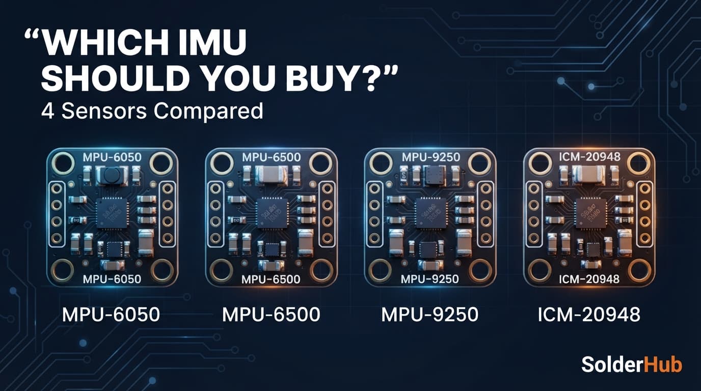
Search for an IMU for an Arduino or ESP32 project and the same four names keep appearing: the MPU-6050, the MPU-6500, the MPU-9250 and the ICM-20948. Plenty of guides treat them as interchangeable ('buy whichever is cheaper'), and that advice breaks down in two places: the difference between 6-axis and 9-axis sensing, and the fact that the module you receive is not always the chip printed on the listing.
This guide explains what the axes actually measure, where the MPU-6050 and MPU-6500 really differ, what a magnetometer adds, how to check which chip is on your board, and which sensor suits which job. It also covers the sourcing reality: TDK InvenSense has discontinued the MPU-6050 and the MPU-9250, which changes what makes sense for a product compared with a weekend build.
The Quick Answer
| You need | Pick | Why |
|---|---|---|
| Learning, tilt, a balancing robot, lowest cost | MPU‑6050 | Cheapest, simplest wiring, a decade of tutorials |
| The same job with SPI, lower power or a smaller board | MPU‑6500 | Same 6-axis idea in a smaller package, adds SPI |
| A compass heading, with existing MPU‑9250 code | MPU‑9250 | Fine for a one-off build, if the module is genuine |
| A new 9-axis design | ICM‑20948 | The current TDK part, with full 9-axis fusion in its DMP |
| Orientation without writing fusion code | BNO055 | Fusion runs on the chip and returns Euler angles or quaternions |
The rest of this guide explains why, and how to avoid buying the wrong chip.
What 6-Axis and 9-Axis Actually Measure
Every sensor here is built from combinations of three 3-axis MEMS devices:
- Accelerometer (3 axes): measures linear acceleration on X, Y and Z, including the constant 1 g pull of gravity. That is how a stationary sensor knows which way is down and derives tilt (pitch and roll).
- Gyroscope (3 axes): measures angular velocity, how fast the sensor is rotating around each axis, not its absolute angle. Angle has to be calculated by integrating that rate over time.
- Magnetometer (3 axes): measures the local magnetic field, which, away from interference, points toward magnetic north. It is the only one of the three that gives an absolute reference for yaw (compass heading).
'6-axis' means accelerometer plus gyroscope. '9-axis' adds the magnetometer. That addition matters more than the number suggests. A gyroscope's angle estimate drifts because small errors accumulate every time you integrate, and the accelerometer's gravity reference constrains only pitch and roll, so it says nothing about which way the sensor faces around the vertical axis. Without a magnetometer, yaw drifts indefinitely with nothing to correct it. That is why a 6-axis sensor paired with a complementary or Kalman filter gives stable pitch and roll but still drifts in yaw however good the filter is. Only a magnetometer, or an outside reference such as GPS heading, fixes that.
Side-by-Side Comparison
| Spec | MPU‑6050 | MPU‑6500 | MPU‑9250 | ICM‑20948 |
|---|---|---|---|---|
| Axes | 6 (accel + gyro) | 6 (accel + gyro) | 9 (accel + gyro + mag) | 9 (accel + gyro + mag) |
| Magnetometer | None | None | AK8963, a separate die in the same package | AK09916, a separate die in the same package |
| Interface | I2C only | I2C or SPI | I2C or SPI | I2C or SPI |
| I2C address | 0x68 or 0x69 (AD0 pin) | 0x68 or 0x69 | 0x68 or 0x69 | 0x68 or 0x69 |
| WHO_AM_I value | 0x68 | 0x70 | 0x71 | 0xEA |
| Package | 24-QFN, 4x4 mm | 24-QFN, 3x3 mm | 24-QFN, 3x3 mm | 24-QFN, 3x3 mm |
| Onboard motion processor (DMP) | Yes, 6-axis | Yes, 6-axis | Yes, accel and gyro only | Yes, full 9-axis fusion |
| Status | Discontinued by TDK, not recommended for new designs | Older generation, check availability | End of life (TDK announced production ending by the end of 2018) | Current TDK part, the official successor to the MPU‑9250 |
| Library depth | Enormous | Good, most drivers treat it like a 6050 | Good, common in drones and robotics | Growing, not register-compatible with the 9250 |
The pattern to notice: nearly every chip that tutorials name is obsolete from the manufacturer's side. That does not make them bad choices, because third-party modules remain cheap and widely stocked, but it does mean the ICM-20948 is the one in this group worth designing a long-lived product around.
MPU-6050: Still the Default for a Reason
The MPU-6050 earns its popularity. It is the cheapest option, the I2C wiring is as simple as sensors get, and its onboard Digital Motion Processor can handle basic accel and gyro fusion in hardware, which helps when the host is something modest like an Arduino Uno.
Good for: self-balancing robots, tilt and shake demos, classroom and learning projects, and anything where a working six-axis sensor is the whole requirement.
The real limitation is the clone market, not the chip. Because it is so widely copied, gyro bias and noise vary between modules from different sellers. Zero-offset calibration at start-up is effectively mandatory if you want stable readings (code below).
MPU-6500: A Smaller, Lower-Power 6050, Not a Different Class
The MPU-6500 has the same six axes in a smaller 3x3 mm package and adds SPI. It is close enough to the 6050 at the register level that the Linux kernel's inv_mpu6050 driver supports both.
On paper it is not a clear upgrade. TDK's datasheet figure for gyro noise is 0.01 dps/√Hz on the 6500 against 0.005 dps/√Hz on the 6050, so do not choose it expecting a quieter gyro. Its real advantages are lower accelerometer noise (300 µg/√Hz against 400 µg/√Hz), lower power draw, the smaller package and SPI. For a hobby project the choice mostly comes down to which one a seller you trust has in stock.
Good for: wearables and small battery builds, or anything that needs SPI. Otherwise treat it as interchangeable with the 6050.
Check What You Actually Bought
Many modules sold as an MPU-9250 carry an MPU-6500, which has no magnetometer, and some sold as MPU-6050 are other chips again. You can tell by reading the WHO_AM_I register over I2C. The sketch below works for the MPU family and prints the chip's ID.
Wire the module first (SDA and SCL are the board's I2C pins):
| Board | SDA | SCL |
|---|---|---|
| Arduino Uno or Nano | A4 | A5 |
| Arduino Mega | 20 | 21 |
| ESP32 (default) | GPIO 21 | GPIO 22 |
| ESP8266 NodeMCU or D1 Mini | D2 (GPIO 4) | D1 (GPIO 5) |
Most GY-521 style breakouts include a regulator and pull-up resistors and accept 3.3 V or 5 V power. Check your module before assuming that, and use 3.3 V logic on an ESP board.
| Reads | Chip |
|---|---|
| 0x68 | MPU‑6050, or an MPU‑9150 relabelled as an MPU‑9250 |
| 0x70 | MPU‑6500 (a 'MPU‑9250' module that reads this has no magnetometer) |
| 0x71 | MPU‑9250 |
| 0x73 | MPU‑9255 |
The ICM-20948 is different. It uses register banks, and its WHO_AM_I sits at register 0x00 and reads 0xEA, so use its own library to check it. If a listing says 9-axis and you got 0x70 or 0x68, you have a 6-axis chip.
The 9-Axis Family: MPU-9250, ICM-20948 and BNO055
MPU-9250 is an MPU-6500 die and an AK8963 magnetometer die in one package. The magnetometer is reached through the main chip's auxiliary I2C bus, which is why some libraries initialize it as if it were two devices. TDK announced its end of life with production ending by the end of 2018 and named the ICM-20948 as the replacement.
The ICM-20948 pairs newer InvenSense accelerometer and gyro silicon with an AK09916 magnetometer. TDK's migration note is explicit that its registers differ from the MPU-9250, so existing firmware needs a real driver swap, not just a part-number change. The bare ICM-20948 chip also limits its I/O voltage (VDDIO) to 1.71 to 1.95 V, while the MPU-9250 accepts up to VDD. Most breakout boards add their own regulation and level shifting, so this only matters if you are designing a PCB around the bare chip.
BNO055 (Bosch) is the 'it just works' alternative. It runs its own processor doing full sensor fusion and returns absolute orientation, as Euler angles or quaternions, over I2C. There is no fusion algorithm to write, tune or debug. The tradeoffs are a higher price than a bare MPU-9250 or ICM-20948 breakout and uneven availability, so check current stock before committing a design to it.
Of these three, the ICM-20948 is the one to build a new, long-lived project around. The MPU-9250 and BNO055 remain usable for a one-off build.
Choosing by Use Case
| Use case | Recommendation | Why |
|---|---|---|
| Self-balancing robot or RC car stabilization | MPU‑6050 or MPU‑6500 | Only relative tilt matters, no absolute heading is needed |
| Step counter, tap or shake detection | MPU‑6050 or MPU‑6500 | The onboard motion detection covers it without extra fusion code |
| Drone or flight controller | MPU‑6050 or MPU‑6500 is usually enough | Flight stabilization relies on accel and gyro. Many racing drones skip the magnetometer because motor and ESC current disturbs it |
| Digital compass or heading indicator | 9-axis (ICM‑20948, MPU‑9250) | The magnetometer is the entire point. A 6-axis sensor cannot do this |
| AR/VR head or hand tracking | 9-axis, ideally with onboard fusion (BNO055) | Offloading fusion to the sensor saves host CPU on a wearable |
| Indoor navigation or dead-reckoning | 9-axis, with realistic expectations | Heading is needed, but steel and electronics indoors make it hard whatever the sensor |
| Camera gimbal | Depends on scope | Stabilizing relative to the camera body: 6-axis is fine. Holding an absolute bearing: 9-axis |
The Gotcha in Every 9-Axis Project: Magnetometer Interference
A magnetometer measures the total local magnetic field, not just the Earth's. Hard-iron interference (a fixed offset from nearby magnets or ferrous metal) and soft-iron interference (field distortion from nearby electronics or current-carrying wiring) both corrupt the heading. A 9-axis sensor mounted near a motor, speaker, battery pack or even a USB cable carrying current picks up an offset that a plain gyro and accelerometer never see.
That is why every 9-axis project needs a calibration routine: rotate the sensor through all orientations while logging the minimum and maximum field on each axis, then compute an offset and scale correction. It is the most common reason behind 'my compass reading is wrong' questions, and it has nothing to do with a faulty sensor.
What the Code Looks Like
A 6-axis sensor hands you raw numbers. Turning them into a stable angle is your job. With Adafruit's MPU6050 library, first read the values:
Then remove the gyro's resting offset. Keep the sensor perfectly still while this runs at start-up, and subtract the result from every later reading:
Finally, a complementary filter blends the gyro's smooth short-term angle with the accelerometer's drift-free long-term tilt. Axis choice depends on how the module is mounted, so treat this as a pattern, not a drop-in:
The chart below runs this filter on simulated data so you can see what it buys you. The gyro alone drifts away from the true angle, the accelerometer alone is noisy, and the blend tracks the true angle closely. The right-hand panel shows the limit of any 6-axis fix: yaw has no absolute reference, so it keeps wandering until a magnetometer corrects it.
A BNO055 skips all of that. Fusion runs on the chip, so one call returns the heading:
The goal is the same in both cases, knowing which way the sensor points. One hands you raw numbers to fuse yourself and the other hands you the answer.
Verdict
If the project needs only tilt, shake or relative rotation (a balancing robot, a tilt-controlled game, a basic flight controller), the MPU-6050 is a reasonable choice, and the MPU-6500 is an equally valid, slightly smaller alternative if it is what is in stock.
If the project needs an absolute heading (a compass, AR/VR tracking, navigation), a 9-axis sensor is not optional. Between the options, the ICM-20948 is the one to build around if the project will outlive a single prototype. The MPU-9250 is fine for a one-off build using existing tutorials and code, provided you have confirmed with WHO_AM_I that the module is genuine.
If you do not want to write and tune a fusion algorithm at all, the BNO055's onboard fusion is worth the extra cost.
Quick Answers to Common Questions
What is the difference between the MPU-6050 and MPU-6500? Same six axes. The MPU-6500 is smaller, uses less power, has lower accelerometer noise and adds SPI. It does not have a quieter gyro on paper. The MPU-6050 is I2C only.
Is the MPU-6050 discontinued? Yes. TDK InvenSense has discontinued the chip and does not recommend it for new designs. Third-party modules remain widely stocked and it is still a fine choice for hobby projects.
Does the MPU-6050 have a magnetometer? No. It measures acceleration and rotation only, so its yaw angle drifts. For a compass you need a 9-axis sensor.
Is the MPU-9250 compatible with ICM-20948 code? No. The registers differ, so existing firmware needs a driver change.
How do I know if my MPU-9250 is real? Read WHO_AM_I. A genuine MPU-9250 returns 0x71. A 0x70 means an MPU-6500 with no magnetometer, and 0x68 means a 6050-class chip.
Can I use an MPU-6050 for a drone? Yes. Most flight controllers use 6-axis sensors for stabilization, and many racing drones skip the magnetometer because of motor interference.
Do I need 9 axes for a self-balancing robot? No. Pitch and roll from a 6-axis sensor are all balancing needs. Yaw drift does not affect staying upright.
Why does my 9-axis compass read wrong or drift? Almost always uncalibrated hard-iron or soft-iron interference from nearby metal, motors or current-carrying wiring. Run a full calibration before trusting the heading.
Where to Go From Here
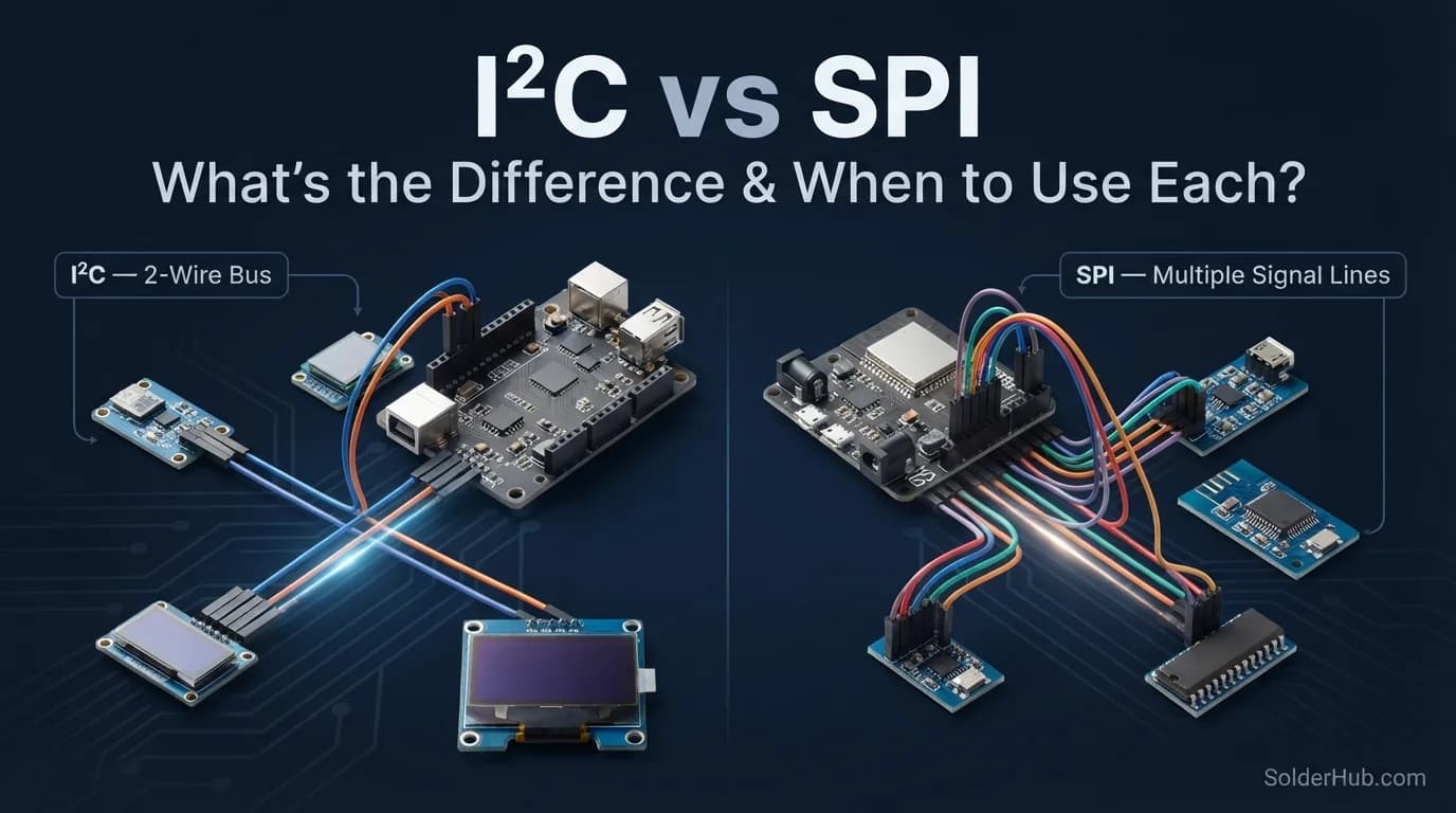
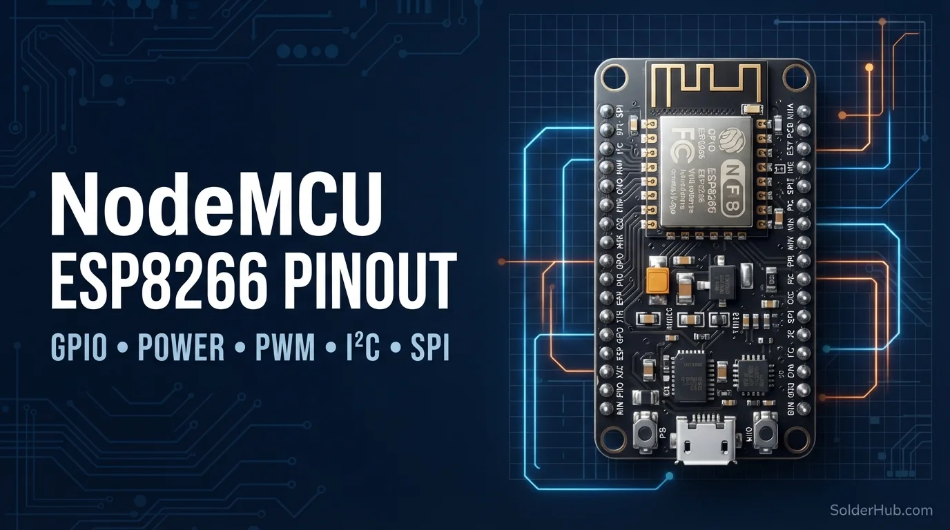
Once you have chosen a sensor, the next real investment is calibration: a gyro zero-offset routine for any 6-axis sensor, and a full hard-iron and soft-iron pass for any 9-axis sensor. Skipping either is the usual reason a working sensor still gives unstable results in a finished project. If you are wiring the sensor to an Arduino, the MPU6050 with Arduino Uno page has the connections. For the bus itself, the I2C vs SPI guide explains when each makes sense, and the ESP32 pinout guide shows which pins to use if the sensor goes on an ESP32.
Sources and Further Reading
- TDK InvenSense MPU-6500 product page: the manufacturer's page, which labels the part for legacy designs.
- TDK application note AN-000146: migrating from the MPU-9250 to the ICM-20948: register, pinout and voltage differences between the two parts.
- Compatibility between the MPU-9250 and ICM-20948: TDK's community Q&A on swapping one for the other.
- The MPU-6050 and MPU-6500 datasheets (TDK InvenSense, document numbers PS-MPU-6000A and PS-MPU-6500A) for the noise-density figures shown in the noise chart.
The drift and calibration charts are simulations built to illustrate the behaviour described above, not measurements from a specific module. Real sensors vary with temperature, mounting and the individual chip.