

Motion
Interfacing MPU-6050 Motion with arduino-uno
What is the MPU-6050?
MPU-6050 practical reference
The MPU-6050 is a six-axis inertial measurement unit (IMU) that combines a 3-axis accelerometer and a 3-axis gyroscope in one chip. The common GY-521 breakout exposes the sensor over I²C and usually includes supporting components such as a voltage regulator and pull-up resistors. The chip also includes a temperature sensor.
Use the accelerometer to measure acceleration (including gravity), the gyroscope to measure angular velocity, and I²C to read the data from a microcontroller. These raw readings do not automatically provide reliable yaw, pitch and roll; orientation estimates require calculations and usually sensor fusion.
Accelerometer vs. gyroscope
- Accelerometer (X, Y, Z): reports acceleration along three axes. When stationary, gravity contributes to the reading, which can help estimate tilt. Motion and vibration also affect the result.
- Gyroscope (X, Y, Z): reports angular velocity, typically in degrees per second or radians per second. Integrating these values estimates rotation but accumulates drift over time.
- Temperature: the chip's internal temperature measurement can help characterize the sensor, but it is not a calibrated ambient-temperature probe.
The MPU-6050 is useful for robot balancing, gesture experiments, vibration monitoring, motion logging and learning about inertial sensing. It is not a GPS, compass or direct absolute-heading sensor.
I²C address and communication
The default 7-bit address is usually 0x68. If the AD0 pin is driven HIGH, the address commonly becomes 0x69. Some example sketches and libraries use the 7-bit address, not the shifted 8-bit read/write address.
I²C requires SDA, SCL, a shared ground and suitable pull-up resistors. Many GY-521 boards already include pull-ups, but clones may connect them to different rails. Before connecting to an ESP32 or another 3.3 V MCU, verify that SDA and SCL are never pulled up to 5 V. Use a proper bidirectional I²C level shifter if the breakout's logic levels are incompatible.
Common projects
- Self-balancing robot: combine accelerometer and gyroscope data with a control algorithm and motor driver.
- Gesture controller: detect tilt or motion patterns and map them to commands.
- Vibration logger: record acceleration changes over time to compare operating conditions.
- Motion-controlled interface: use orientation estimates to trigger menu actions or control a small game.
- Data logger: send readings to serial output, an SD card or a wireless dashboard.
Start by confirming that the sensor responds over I²C, then collect stable readings while the board is stationary. Add filtering or sensor fusion only after the raw data makes sense.
Best practices
- Mount it firmly. Loose wiring or a flexing board can appear as vibration or motion.
- Keep the I²C wires short. Long leads and noisy motor wiring can cause communication errors.
- Check logic levels. This matters especially when pairing a 5 V Arduino with a 3.3 V sensor breakout or an ESP32.
- Use sensible ranges. A wider full-scale range avoids clipping but reduces sensitivity for small movements.
- Calibrate when needed. Gyroscope bias and accelerometer offsets vary between modules; collect stationary samples and account for offsets in software.
- Do not call raw gyro integration absolute orientation. Gyroscope bias accumulates; use an appropriate fusion method if you need stable attitude estimates.
- Avoid unsupported library assumptions. Use the board-specific I²C pins and verify the library version and address configuration.
Troubleshooting
| Symptom | Likely cause | Check |
|---|---|---|
| Sensor not found | Wrong address, wiring, power or ground | Run an I²C scanner; check SDA/SCL and try 0x68/0x69 as appropriate. |
| Readings stay at zero | Sensor not initialized or incorrect bus pins | Confirm mpu.begin() succeeds and use the correct Wire pins. |
| ESP32 resets or bus hangs | Incorrect logic voltage or wiring noise | Verify SDA/SCL pull-ups are 3.3 V-safe and shorten wires. |
| Accelerometer values change at rest | Board tilt, vibration or offsets | Place it still on a level surface and inspect all axes; gravity should be visible on one axis. |
| Gyroscope never reads exactly zero | Normal bias and noise | Average stationary samples and calibrate offsets if needed. |
| Values clip during movement | Selected full-scale range is too small | Choose a wider accelerometer or gyroscope range. |
Frequently asked questions
Does the MPU-6050 measure yaw, pitch and roll directly? No. It reports acceleration and angular velocity. Orientation must be estimated in software; yaw especially drifts without an external reference such as a magnetometer.
Is a library required? No library is strictly required for raw I²C access, but the Adafruit MPU6050 library makes beginner projects simpler.
What is the default I²C address? Usually 0x68, with 0x69 commonly selected by setting AD0 HIGH.
Can I connect it to an ESP32? Yes, with compatible power and 3.3 V-safe I²C lines. Do not assume a breakout's VCC input rating also guarantees 5 V-safe SDA/SCL.
Is the simulator a full IMU emulator? No. The SolderHub project is a wiring and orientation teaching aid. It does not emulate real I²C register transactions, gyroscope drift or a full sensor-fusion algorithm.
Key specifications
- Sensor type: 6-axis IMU: 3-axis accelerometer plus 3-axis gyroscope.
- Interface: I²C; commonly address 0x68, or 0x69 when AD0 is HIGH.
- Accelerometer range: Selectable ±2 g, ±4 g, ±8 g, or ±16 g.
- Gyroscope range: Selectable ±250, ±500, ±1000, or ±2000 degrees/second.
- Supply / logic: Bare chip is a low-voltage device; breakout power and logic-level compatibility depend on the specific board. Verify before connecting to 5 V logic.
- Orientation output: Raw acceleration and angular velocity; pitch/roll/yaw require software estimation and sensor fusion.
Pinout and connection notes
The MPU-6050 chip itself is not 5 V tolerant. Common GY-521 breakouts may include a regulator and pull-ups, but clone layouts vary. Verify SDA/SCL pull-up voltage and module supply before wiring to an Uno or ESP32.
- Power: Supply according to the exact breakout documentation; do not assume all GY-521 clones have identical regulation.
- Ground: Connect to the controller ground.
- I²C data: Connect to the controller SDA pin and ensure pull-ups do not exceed the sensor logic voltage.
- I²C clock: Connect to the controller SCL pin and ensure pull-ups do not exceed the sensor logic voltage.
- Address select: Typically selects 0x68 when LOW and 0x69 when HIGH.
- Interrupt: Optional interrupt output; use only if the firmware configures it.
- Auxiliary I²C: Auxiliary sensor bus pins; not required for basic host I²C readings.
Integration checklist
- Confirm the exact part number and breakout-board revision.
- Verify supply voltage, current demand, logic levels, and signal direction against the datasheet.
- Check controller pin assignments and bus address or interface mode against the example code.
- Power up with external loads disconnected, then test signals before full integration.
- If readings or communication fail, check power and ground first, then pin mapping, interface settings, and library initialization.
Troubleshooting and reproducibility
Record the board used, wiring, library/version, supply arrangement, and measured behavior. Use the selected board-specific wiring example as the source of truth. Never assume visually similar modules share identical voltage tolerance or pin order.
Setting Up MPU-6050 with arduino-uno
Library
Adafruit MPU6050 by Adafruit
Arduino IDE Library Manager: Adafruit MPU6050; install Adafruit Unified Sensor and Adafruit BusIO dependencies as prompted.
Read acceleration, angular velocity and chip temperature from a GY-521 MPU-6050 using an Arduino Uno over I²C. This example uses the Adafruit MPU6050 library and prints raw sensor measurements to Serial Monitor. It does not calculate fused yaw, pitch and roll.
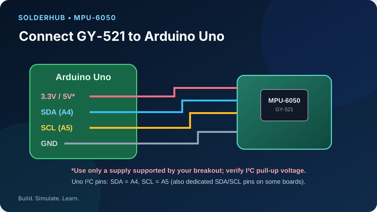
MPU-6050 to Arduino Uno
| GY-521 pin | Uno connection | Notes |
|---|---|---|
| VCC | 5V or 3.3V, per module rating | Only use 5V if the breakout explicitly supports it. |
| GND | GND | Common ground. |
| SDA | A4 / SDA | I²C data. |
| SCL | A5 / SCL | I²C clock. |
| AD0 | GND or leave as module recommends | LOW commonly selects address 0x68. |
Swipe sideways to see every column →
Try this circuit — SolderHub Simulator
The circuit is preloaded for exploration. Confirm simulator behavior against the real wiring and sensor datasheet before connecting hardware.
Install the library
In Arduino IDE, open Library Manager and install Adafruit MPU6050. Install its required dependencies if the IDE prompts you, including Adafruit Unified Sensor and Adafruit BusIO. Select Arduino Uno and the correct serial port.
- 1With power disconnected, connect SDA to A4 and SCL to A5; connect VCC and GND according to your breakout's ratings.
- 2Verify the breakout's SDA/SCL idle voltage is safe for the Uno and that the sensor and Uno share ground.
- 3Install Adafruit MPU6050 from Arduino IDE Library Manager and accept the required dependencies.
- 4Upload the sketch and open Serial Monitor at 115200 baud.
- 5Keep the board still and note the acceleration values; gravity should appear mainly on one axis when level.
- 6Rotate the board slowly and observe the accelerometer and gyroscope readings change.
Expected output
The sketch prints three accelerometer values in m/s², three gyroscope values in rad/s, and the sensor's temperature. At rest, the accelerometer still measures gravity. Gyroscope readings may hover around small non-zero values because of bias and noise.
Troubleshooting
- MPU not found: check A4/A5, power, common ground and address. Try an I²C scanner to confirm 0x68 or 0x69.
- Values unstable: keep the module still, shorten wires and move it away from motors.
- No compile: confirm the Adafruit MPU6050, Adafruit Unified Sensor and Adafruit BusIO libraries are installed.
- Hot or unresponsive module: disconnect power and recheck VCC and logic wiring before trying again.
Related Components


Related Guides & Projects
Arduino Uno R4 Minima Pinout: Every GPIO, ADC, DAC, and Op-Amp Pin Explained
A complete Arduino Uno R4 Minima pinout reference — digital I/O, ADC, DAC, op-amp, CAN, dual UART, and exactly what it leaves out compared to the WiFi variant.
Mastering PWM on Arduino: Dimming LEDs and Controlling Motors
Understand what PWM actually is on Arduino, dim an LED smoothly, and safely control a DC motor's speed with a driver chip -- plus the mistakes (like wiring a motor straight to a pin) that damage boards.
4-Digit 7-Segment Counter with TM1637 & Arduino
Drive a TM1637-based 4-digit 7-segment display with Arduino Uno to show a real-time up/down counter, elapsed timer, and scrolling text. Covers library setup, brightness control, and custom segment mapping.
Arduino Uno R4 Minima vs WiFi: Which One Should You Choose?
Same processor, same memory, different price. Here's what the WiFi variant's extra hardware actually gets you, and when the Minima is the smarter buy.