I2C vs SPI: What's the Difference and When to Use Each
The first time I had to choose between I2C and SPI for a project, I genuinely just picked whichever one had more example code for the sensor I was using. That's a fine way to get something working in an afternoon, but it's a terrible way to actually understand what you're doing — and eventually you hit a project where the wrong choice costs you real time. A sensor that's too slow over I2C. A wiring mess from too many SPI chip-select lines. A library that doesn't behave the way you expected.
So let's actually break this down properly — what these two protocols are, how they differ under the hood, and which one makes sense for the project sitting in front of you.
[INSERT IMAGE HERE: Side-by-side wiring diagram comparing I2C and SPI connections to a microcontroller]
The Short Version
I2C and SPI are both protocols for short-distance communication between a microcontroller and peripheral chips — sensors, displays, EEPROMs, ADCs, you name it. Both have been around for decades, both are everywhere in hobby electronics and commercial products alike, and neither one is "better" in any absolute sense. They just make different tradeoffs, and once you understand those tradeoffs, picking between them stops being a guessing game.
I2C trades speed for simplicity in wiring. SPI trades wiring simplicity for speed. That's really the heart of it — everything else is detail.
What Is I2C?
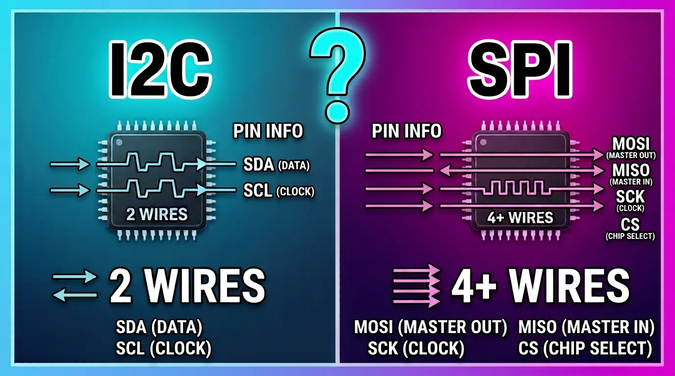
I2C (Inter-Integrated Circuit, often pronounced "I-squared-C") was developed by Philips back in the 1980s for connecting chips on the same circuit board without needing a dedicated wire for every device. It uses just two wires for communication, no matter how many devices are on the bus:
- SDA (Serial Data) — carries the actual data
- SCL (Serial Clock) — keeps every device in sync
[INSERT IMAGE HERE: Diagram of an I2C bus with one microcontroller and three sensors all sharing SDA and SCL lines]
Here's the clever part: every device on the bus has its own unique address. The microcontroller (the "master") sends out an address on the SDA line, and only the device that matches that address responds. Everything else on the bus just ignores the conversation. This is why you can wire up five or six sensors using only two wires total — they all share the same physical lines and just listen for their own address.
How I2C Communication Actually Works
- The master pulls SDA low to signal the start of a transmission
- It sends the 7-bit (or sometimes 10-bit) address of the device it wants to talk to
- The target device acknowledges by pulling SDA low for one clock cycle
- Data gets exchanged byte by byte, with an acknowledgment after each byte
- The master signals a stop condition to end the transaction
It's a fairly chatty protocol — all that addressing and acknowledging adds overhead, which is part of why I2C tends to be slower than SPI in practice.
I2C Speed
Standard I2C runs at 100 kHz ("Standard Mode"), with faster variants pushing to 400 kHz ("Fast Mode"), 1 MHz ("Fast Mode Plus"), and up to 3.4 MHz ("High Speed Mode") on supporting hardware. In real hobby projects, you'll mostly see devices running at 100 kHz or 400 kHz.
What Is SPI?
SPI (Serial Peripheral Interface) was developed by Motorola, and it takes a different approach entirely. Instead of sharing two wires among every device, SPI uses four lines, and adds one extra wire per additional device:
- MOSI (Master Out, Slave In) — data from master to peripheral
- MISO (Master In, Slave Out) — data from peripheral back to master
- SCLK (Serial Clock) — clock signal, same idea as I2C's SCL
- CS / SS (Chip Select / Slave Select) — one per device, used to "wake up" the specific chip you want to talk to
[INSERT IMAGE HERE: Diagram of an SPI bus with one microcontroller and multiple peripherals, each with its own chip-select line]
Instead of addressing a device over the shared data line like I2C does, SPI physically selects which device is "listening" by pulling its dedicated CS line low. Only one device is active at a time, and because there's no addressing handshake, no acknowledgment bits, and a much simpler protocol overall, data moves a lot faster.
How SPI Communication Actually Works
- The master pulls the target device's CS line low, activating it
- Data is clocked out on MOSI and clocked in on MISO simultaneously — SPI is full-duplex, meaning it can send and receive at the same time
- Once the transaction finishes, CS goes high again, deactivating that device
There's no addressing step, no acknowledgment byte, no stop condition to manage. It's a much leaner protocol, and that simplicity is exactly why it's so fast.
SPI Speed
SPI doesn't really have a standardized speed ceiling the way I2C does — it's largely limited by the capabilities of the specific chips involved and the quality of your wiring. Many SPI devices comfortably run at 10 MHz or higher, with some pushing into the tens of MHz range. This is roughly an order of magnitude faster than typical I2C setups.
The Core Differences, Side by Side
| I2C | SPI | |
|---|---|---|
| Wire count | 2 (shared across all devices) | 4 + 1 per extra device |
| Speed | Slower (100 kHz–3.4 MHz typical) | Faster (often 10+ MHz) |
| Addressing | Software-based, via device address | Hardware-based, via dedicated CS line |
| Duplex | Half-duplex | Full-duplex |
| Device limit | Practically dozens, address-limited | Limited mostly by available GPIO pins |
| Complexity | Slightly more complex protocol, simpler wiring | Simpler protocol, more wiring |
| Power use | Generally lower | Generally higher at high speeds |
| Error checking | Built-in acknowledgment bits | None built in — up to you |
[INSERT IMAGE HERE: Clean comparison table graphic of I2C vs SPI specs]
Wiring: Where the Real-World Difference Hits Hardest
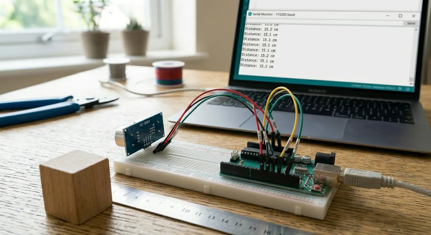
This is where the choice actually shows up on your breadboard. With I2C, adding a fourth, fifth, or sixth sensor to your project means adding exactly zero new wires to your microcontroller — you just tap into the same SDA and SCL lines. I've built sensor-heavy projects where this alone made I2C the obvious pick; routing four extra wires per device would have turned a tidy build into a rat's nest.
SPI doesn't scale the same way. Every additional device needs its own CS pin back to the microcontroller, on top of the three shared lines (MOSI, MISO, SCLK). On a microcontroller with limited GPIO — something like an ATtiny or a small ESP variant — this adds up fast and can become the actual limiting factor in your design, not the processing power.
[INSERT IMAGE HERE: Breadboard photo showing multiple sensors wired via I2C with minimal wiring]
Speed and Real-Time Use Cases
If your project involves anything time-sensitive — a high-resolution ADC streaming samples, an SD card needing fast read/write, a display that needs to refresh smoothly without visible lag — SPI is usually the right call. Displays in particular almost always use SPI (or the wider parallel bus on bigger screens) because pushing a full frame of pixel data over I2C's slower bus would mean visible, frustrating lag.
I2C, meanwhile, is plenty fast for anything that doesn't need rapid, continuous data. Temperature sensors, humidity sensors, real-time clocks, EEPROMs you read from occasionally — these all generate small amounts of data infrequently, and I2C's lower speed simply doesn't matter for them.
Addressing Conflicts: A Real Headache With I2C
One problem that catches people off guard with I2C: device address collisions. If you wire up two identical sensors — say, two of the same temperature sensor model — they'll often ship with the same fixed I2C address by default. The bus has no way to tell them apart, and your code will either talk to the wrong one or just fail outright.
Some sensors solve this with an address-select pin you can wire high or low to choose between two addresses. Others don't offer that flexibility at all, which means you're stuck using an I2C multiplexer chip to work around the collision. It's a genuinely annoying problem that SPI simply doesn't have — since each device gets its own dedicated CS line, there's never any ambiguity about which device you're talking to.
[INSERT IMAGE HERE: Close-up of a sensor breakout board showing an address-select solder jumper or pin]
Power Consumption Considerations
For battery-powered projects, this matters more than people expect. I2C's lower clock speeds generally mean lower power draw, which is part of why it's the default choice for so many low-power sensor breakouts. SPI's higher speeds can pull more current, particularly at higher clock rates — something worth factoring in if you're building anything meant to run for weeks on a coin cell or small LiPo battery.
Error Handling: Built-In vs. DIY
I2C has acknowledgment bits baked into the protocol — after every byte, the receiving device confirms it actually got the data. This gives you a basic, automatic way to detect if a device didn't respond or a wire came loose.
SPI has no such mechanism by default. If a wire's disconnected or a device misbehaves, SPI won't tell you — your code will just receive garbage data or nothing at all, and it's on you to build in your own validation if that matters for your project. This isn't necessarily a flaw in SPI's design; it's just a deliberate tradeoff for keeping the protocol fast and simple.
So, Which One Should You Actually Use?
Here's the practical way I think about it now, after enough projects to have learned this the slow way:
Reach for I2C when:
- You're connecting several different sensors and want minimal wiring
- Speed isn't critical — you're reading temperature, humidity, light levels, or similar slow-changing data
- You're working with a microcontroller that has limited GPIO pins
- The sensor you're using only comes in an I2C version (very common)
Reach for SPI when:
- You need high data throughput — displays, SD cards, high-speed ADCs/DACs
- You only have a small number of peripherals, so the extra CS wiring isn't a burden
- Low latency genuinely matters for your application
- The device you're using only comes in an SPI version (also very common — many displays and flash memory chips are SPI-only)
And realistically: a lot of the time, the chip you're using simply only supports one protocol or the other, and the decision gets made for you. In those cases, this whole comparison is mostly about understanding why the datasheet specifies what it specifies — which makes wiring it correctly, and debugging it when something goes wrong, a whole lot less mysterious.
[INSERT IMAGE HERE: Flowchart-style graphic helping decide between I2C and SPI based on project needs]
A Quick Note on Mixing Both
Plenty of real projects use both protocols at once — an I2C sensor cluster for environmental readings alongside an SPI display for showing the results, for example. Most modern microcontrollers, including the Pi's GPIO header and boards like the ESP32, support both simultaneously without conflict, since they use entirely separate sets of pins. There's no rule saying you have to commit to one protocol for an entire project — pick whichever fits each individual component.
Final Thoughts
Neither I2C nor SPI is the "correct" choice in some universal sense — they're just two different answers to the same problem, built with different priorities. I2C optimizes for simple wiring and scalability; SPI optimizes for raw speed. Once you've wired up a few projects with each, the choice stops feeling like trivia and starts feeling obvious based on what the project actually needs.
Next time you're staring at a sensor's datasheet trying to figure out which protocol it speaks, you'll already know exactly why it was built that way — and exactly what tradeoff you're signing up for.
Happy soldering.