

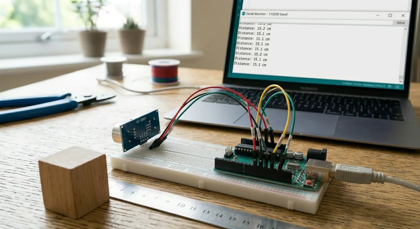
What You'll Build
A pocket-sized digital distance meter: point the sensor at a wall, your hand, or a box, and the Arduino Uno shows the distance in centimetres on an I2C 16x2 (1602) LCD — updated several times a second, with a live bar graph on the second row.
Thanks to the I2C backpack on the display, the LCD needs only four wires (power, ground, SDA, SCL) instead of the twelve a plain 1602 requires. That leaves the rest of the Uno's pins free for future upgrades.
No computer is needed once the sketch is uploaded. Power it from a USB power bank and it becomes a portable ruler for 2 cm to about 4 m.
What you will learn:
- How the HC-SR04 turns a burst of ultrasound into a distance
- How to connect an I2C LCD to an Arduino Uno and find its I2C address
- How to write a stable measurement routine (timeouts, median filtering, temperature compensation)
- How to format numbers cleanly on a 16-character display
- How to debug the most common wiring, address and contrast problems
Difficulty: Beginner | Build time: about 25 minutes | Board: Arduino Uno R3
What Is the HC-SR04?
The HC-SR04 is a low-cost ultrasonic ranging module. It has two metal "eyes": one is a transmitter that emits a short burst of 40 kHz sound (far above human hearing), the other is a receiver that listens for the echo. Bats and submarines use the same principle.
| Specification | Value |
|---|---|
| Operating voltage | 5 V DC |
| Operating current | about 15 mA |
| Frequency | 40 kHz |
| Measuring range | 2 cm – 400 cm |
| Ranging accuracy | about 3 mm (ideal conditions) |
| Effective measuring angle | about 15° |
| Trigger input | 10 µs TTL pulse |
| Echo output | TTL pulse, width proportional to distance |
| Recommended cycle | 60 ms or longer between measurements |
The module has four pins: VCC, TRIG, ECHO and GND. Because the Uno's I/O is 5 V, the sensor connects directly — no level shifting is needed on this board.
How the Measurement Works
Every reading is a short conversation between the Arduino and the sensor:
- The Arduino pulls TRIG HIGH for 10 µs.
- The sensor emits eight 40 kHz pulses of ultrasound.
- The sound travels to the nearest object, bounces back, and reaches the receiver.
- The sensor raises ECHO HIGH from the moment the burst leaves until the echo returns.
- The Arduino measures how long ECHO stayed HIGH (using
pulseIn()) and converts that time to a distance.
The Distance Formula
Sound travels at roughly 343 m/s at 20 °C, which is 0.0343 cm per microsecond. The measured time covers the trip to the object and back, so the distance is half of that:
distance (cm) = echo time (µs) × 0.0343 / 2
That is where the well-known shortcut comes from: distance ≈ time ÷ 58.
Why Temperature Matters
The speed of sound changes with air temperature, approximately:
speed (m/s) = 331.3 + 0.606 × temperature (°C)
| Air temperature | Speed of sound |
|---|---|
| 0 °C | 331.3 m/s |
| 20 °C | 343.4 m/s |
| 30 °C | 349.5 m/s |
A 10 °C swing shifts the speed by about 1.8 %, which is roughly 1.8 cm of error at 100 cm. The sketch below includes a TEMP_C constant so you can correct for your room temperature.
Try it in the simulator
Arduino Uno wired to an HC-SR04 (TRIG → D9, ECHO → D10). Select the sensor to change the distance it sees.
Open in full simulator ↗Components
5 itemsUnderstanding the I2C 1602 LCD
A "1602" LCD shows 16 characters on each of 2 rows. The display itself uses the Hitachi HD44780 controller, which normally needs about six signal wires plus power, contrast and backlight connections.
Most modules now come with a small I2C backpack soldered on the back. It contains a PCF8574 port-expander chip that talks to the LCD for you, so the Arduino only has to use the two-wire I2C bus:
| Backpack Pin | Function | Arduino Uno Pin |
|---|---|---|
| GND | Ground | GND |
| VCC | +5 V supply | 5V |
| SDA | I2C data | A4 |
| SCL | I2C clock | A5 |
On the Uno, the hardware I2C pins are fixed: SDA is A4 and SCL is A5 (they are also broken out on the two extra header pins near AREF on the R3 board). The backpack already includes the pull-up resistors the bus needs, so you do not have to add any.
The I2C address
Every device on an I2C bus has an address. Backpacks usually ship as 0x27 (PCF8574) or 0x3F (PCF8574A). Using the wrong address is the number one reason an I2C LCD stays blank, so this guide includes a short scanner sketch that tells you the right one.
The two small controls on the backpack
- Blue trimmer potentiometer — sets the display contrast. Turn it with a small screwdriver.
- Backlight jumper — a small cap across two pins. Leave it on for the backlight to work; removing it turns the backlight off.
Wiring the Circuit
HC-SR04 to Arduino Uno
| HC-SR04 Pin | Arduino Uno Pin |
|---|---|
| VCC | 5V |
| TRIG | Digital Pin 9 |
| ECHO | Digital Pin 10 |
| GND | GND |
I2C LCD to Arduino Uno
| LCD Backpack Pin | Arduino Uno Pin |
|---|---|
| GND | GND |
| VCC | 5V |
| SDA | A4 |
| SCL | A5 |
Build order that avoids mistakes
- Run the Uno's 5V and GND to the breadboard power rails first.
- Connect the four LCD backpack wires (GND, VCC, SDA, SCL).
- Wire the HC-SR04 last, placing it at the board edge so it has a clear view forward.
- Check that no wire crosses the sensor's two "eyes" — anything in front of them can cause false echoes.
💡 Tip
If the LCD backlight is on but you see only a row of solid blocks or a completely blank screen, that is normal until the contrast is set. Use a small screwdriver to turn the blue trimmer on the back of the I2C backpack slowly while the sketch is running until the text appears sharp. This one adjustment solves most "my LCD doesn't work" problems.
Install the LCD Library
The sketches below use the LiquidCrystal I2C library.
- In the Arduino IDE open Sketch → Include Library → Manage Libraries… (or the Library Manager icon).
- Search for LiquidCrystal I2C.
- Install the one by Frank de Brabander.
Wire.h, the library that handles I2C itself, is already built into the Arduino IDE, so nothing else needs installing.
Step 1 — Find the I2C Address
Upload this scanner first. It asks every possible address "is anyone there?" and prints the ones that answer. Open Tools → Serial Monitor at 9600 baud to read the result. This is the only sketch in the project that uses the Serial Monitor, and it exists purely to avoid guessing the address.
Step 2 — Test the LCD on Its Own
Note the address from the scanner (most likely 0x27 or 0x3F). Now prove that the display works before involving the sensor. If this small sketch works, any later problem must be in the sensor wiring or code — not the LCD. This is the most useful debugging habit in electronics: test one subsystem at a time.
If your address is not 0x27, change the value in LCD_ADDR.
Step 3 — The Distance Meter Sketch
This is the complete sketch. It reads the sensor five times, takes the median (so a single bad echo cannot spoil the result), converts the time to centimetres using a temperature-corrected speed of sound, and prints the value with a bar graph on the second row.
Set LCD_ADDR to your scanned address and TEMP_C to your room temperature for best accuracy.
How the Code Works
The LCD object
LiquidCrystal_I2C lcd(LCD_ADDR, 16, 2); tells the library which I2C address to talk to and the display size. After that, lcd.init() starts the display and lcd.backlight() switches the backlight on. All the usual commands (setCursor, print, write, clear) work exactly like on a normal LCD.
Temperature-corrected constant
SOUND_CM_PER_US is calculated once at compile time from TEMP_C. Using a constant means the maths inside the loop is a single multiplication.
readEchoMicros()
This sends the 10 µs trigger pulse and calls pulseIn(ECHO_PIN, HIGH, ECHO_TIMEOUT_US). The third argument is critical: without it, pulseIn() waits up to one full second when nothing is in range, freezing your sketch. With a 25 ms timeout, a missed echo costs almost nothing.
readDistanceCm()
Ultrasonic readings occasionally spike — a stray reflection, a soft surface, electrical noise. Instead of averaging (which a single wild value drags off target), the sketch sorts five readings and takes the median, which simply ignores outliers. A reading of 0 (timeout) is discarded before sorting.
The 60 ms gap between pings follows the datasheet recommendation and prevents the sensor from hearing the echo of its previous burst. Five samples at 60 ms give a fresh result about every 0.3 seconds.
showDistance()
- Every string is padded to exactly 16 characters, so a new value fully overwrites the old one and no leftover digits remain. This is more reliable than calling
lcd.clear()every loop, which causes visible flicker and slows the I2C bus. dtostrf()formats the float with a fixed width, so the decimal point stays in the same column as the number changes from5.2to123.4.- The
F()macro keeps text in flash memory, saving precious Uno SRAM (only 2 KB). - Character code 255 is the solid block in the standard HD44780 character set, which makes the bar graph without any custom characters.
Steps
- 1Wire the HC-SR04 and the I2C LCD exactly as in the wiring tables (LCD SDA to A4, SCL to A5) and double-check 5V and GND before plugging in USB
- 2Install the LiquidCrystal I2C library by Frank de Brabander from the Library Manager
- 3Select Tools → Board → Arduino Uno and the correct COM port, then upload the I2C scanner and note the address
- 4Upload the LCD test sketch, adjust the blue contrast trimmer until the text is clear, and confirm the LCD works
- 5Upload the final distance meter sketch with your LCD_ADDR and TEMP_C values; after the splash screen the LCD should show "Dist: xxx.x cm"
- 6Hold a book or your hand 10 cm, 30 cm and 100 cm in front of the sensor and confirm the reading and the bar both follow
- 7Compare the display with a ruler or tape measure at two or three distances to check your result
Accuracy and Limitations
The HC-SR04 is excellent value, but knowing its limits will save you from chasing phantom bugs:
- Narrow cone, not a laser. The sensor "sees" in a cone of about 15°. At 2 m that cone is roughly 50 cm wide, so it reports the nearest object anywhere inside it.
- Angled surfaces fool it. If the target is tilted more than about 45° away from the sensor, the sound bounces off to the side instead of back, and the reading is wrong or missing.
- Soft materials absorb sound. Fabric, foam, curtains and clothing return a weak echo, so reliable range drops sharply. Hard flat surfaces such as walls, boxes and books work best.
- Very small objects are hard to detect. Thin poles and wires may not reflect enough sound.
- Minimum distance is about 2 cm. Closer than that, the receiver is still "ringing" from the transmitted burst.
- Air temperature and humidity affect results. That is why
TEMP_Cexists. - Realistic range: the specification says 400 cm, but for consistent results on typical targets expect about 2–3 m.
⚠️ Warning
Disconnect the USB cable before changing any wiring. Hot-plugging jumper wires can briefly short a pin to 5V or GND, which can damage the Arduino or the LCD backpack. Also double-check that VCC and GND are not swapped on the HC-SR04 and the LCD backpack before you power up — reversed polarity can destroy either module in seconds.
Troubleshooting
| Problem | Likely Cause | Fix |
|---|---|---|
| Backlight on but display blank or only solid blocks | Contrast set wrong | Turn the blue trimmer on the backpack slowly with a screwdriver |
| Backlight is off and nothing shows | Backlight jumper removed, or no power | Replace the jumper cap on the backpack; check VCC and GND |
| Scanner prints "No I2C devices found" | SDA/SCL swapped, not on A4/A5, or a loose wire | SDA must go to A4 and SCL to A5; reseat the jumpers |
Scanner finds 0x3F but the sketch uses 0x27 | Wrong address in the sketch | Change LCD_ADDR to the scanned address |
Compile error: LiquidCrystal_I2C.h: No such file or directory | Library not installed | Install "LiquidCrystal I2C" by Frank de Brabander from the Library Manager |
| Random or garbled characters | Loose I2C wire or electrical noise | Use shorter, firmly seated jumpers; keep I2C wires away from the sensor wires |
| Display always shows "out range" | TRIG/ECHO swapped, or sensor has no 5V | Confirm TRIG on D9, ECHO on D10, and VCC on 5V |
| Readings jump around by several centimetres | Soft or angled target, or nearby objects inside the cone | Aim at a flat hard surface; keep the cone clear |
| Value is consistently a few centimetres off | Wrong TEMP_C, or the ruler zero isn't aligned with the sensor | Set the real temperature; measure from the front of the transducers |
| Old digits remain at the end of the line | Text not padded to 16 characters | Keep the padded strings used in the sketch |
| Display freezes after a few readings | Missing timeout in pulseIn() | Keep ECHO_TIMEOUT_US in the call |
Ideas to Extend the Project
- Show inches too. Divide the centimetre value by 2.54 and print it on the second row instead of the bar graph.
- Add a hold button. Wire a push button to a free pin with
INPUT_PULLUPand freeze the reading while it is pressed. - Min / max tracking. Store the smallest and largest values seen since power-up and show them on demand.
- Tank level meter. Mount the sensor facing down over a water tank and convert distance to percentage full.
- Add a buzzer for proximity alerts — see the full parking sensor project linked below.
- Smaller changes, big effect. Increase
SAMPLESto 7 for even smoother numbers, or reduce it to 3 for faster updates.
Frequently Asked Questions
My I2C address is not 0x27. What do I do?
Run the scanner sketch and use the address it prints in LCD_ADDR. 0x3F is the other common one.
Can I use other pins for SDA and SCL?
On the Arduino Uno the hardware I2C pins are fixed: SDA is A4 and SCL is A5. TRIG and ECHO, on the other hand, can be any digital pins — just change TRIG_PIN and ECHO_PIN.
Why is it better to use I2C for the LCD? It needs only four wires instead of about twelve, which makes the circuit neater, faster to build, and leaves almost every Uno pin free for other parts.
Why use the median instead of the average? An average is pulled toward a bad reading. If four readings are 30 cm and one is 250 cm, the average is wrong by 44 cm, while the median stays at 30 cm.
Can I power the sensor and LCD from the Uno's 5V pin? Yes. The HC-SR04 draws only about 15 mA and the LCD backpack a little more, which the Uno's USB supply handles comfortably.
Why does the sketch wait 60 ms between pings? Faster than that, the sensor can receive the leftover echo of the previous pulse and report a false, short distance.
What is the actual maximum range? The specification says 400 cm. In practice, with a large flat target, 2–3 m is dependable.
Do I need the temperature constant? No — the meter works fine with the default. It only improves accuracy if your room is much hotter or colder than 25 °C.
My LCD has no backpack and 16 separate pins. Can I follow this guide?
That is a parallel LCD, which needs more wiring and the standard LiquidCrystal library. The sensor logic is identical; only the LCD wiring and initialisation change.
Related on SolderHub
- HC-SR04 Parking Alert with Arduino, LCD & Buzzer
- Arduino Uno R3 Pinout: Every Pin Explained
- Getting Started with Arduino Uno R3 — LED Blink Guide
- Arduino Mega 2560 vs Uno: Which Board Should You Choose?
Published on SolderHub — the electronics platform with live Wokwi simulations, circuit diagrams and production-ready code.