

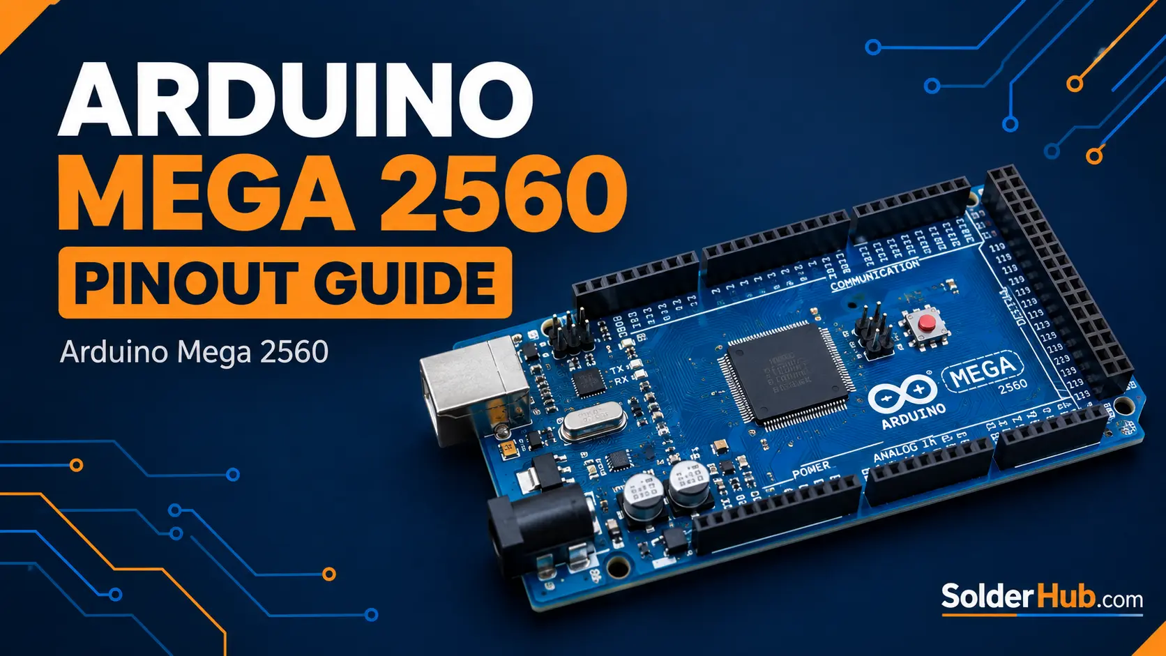
If you've ever stared at an Arduino Mega 2560 and wondered "which pin does what, and why are there so many of them?" — this guide is for you.
The Mega is one of those boards that looks intimidating at first. You pick it up, count 54 digital pins, 16 analog inputs, and a handful of power headers, and suddenly your brain goes into mild panic mode. But here's the thing — once you understand how the pins are grouped and what each group is actually for, the Mega becomes one of the most satisfying boards to work with. It's basically a regular Arduino Uno that went to the gym.
Let's break it all down, section by section, without the jargon overload.
A Quick Word on Why the Mega Exists
The Uno is great. But 14 digital pins and 6 analog inputs run out fast when you're building something real — say, a CNC machine, a 3D printer controller, a robot arm, or any project with more than a handful of sensors and actuators.
The Mega 2560 solves that. It's built around the ATmega2560 microcontroller, running at 16 MHz with 256 KB of flash, 8 KB of SRAM, and 4 KB of EEPROM. That's not just more pins — it's more memory to hold bigger programs, which matters the moment your code starts managing multiple devices at once.
Now let's get into the pins themselves.
Power Pins
Before any signal pin does anything useful, your board needs power. The Mega has a dedicated power header on one side that's easy to overlook but essential to understand.
| Pin | Description |
|---|---|
| VIN | Input voltage when using external power (7–12V recommended, 6–20V accepted) |
| 5V | Regulated 5V output. Available current depends on how the board is powered (see below) |
| 3.3V | Regulated 3.3V output — up to 50mA |
| GND | Ground (five GND pins across the headers, all connected) |
| IOREF | Reference voltage for shields (5V on the Mega) |
| RESET | Pull LOW to reset the microcontroller |
A few things worth knowing here:
The VIN pin works both ways — you can power the Mega through it using an external supply, or read the raw input voltage from it if you're powering via the barrel jack. Most people don't realise this until they need it.
The 3.3V pin is limited to 50mA. That's enough to power a small sensor or a Bluetooth module, but don't try running anything hungry off it — you'll either get noise in your readings or cause a brown-out reset. If you need more 3.3V current, use a separate LDO regulator.
The 5V pin is the board's regulated output, and how much current it can supply depends on how the board is powered. Over USB you're limited by the USB port and the board's 500mA resettable fuse. Over the barrel jack you're limited by the onboard regulator, which gets hot as the input voltage or the load goes up. If you're driving servos, motors or LED strips, use a separate 5V supply (with a shared GND) instead of the board's 5V pin.
There are five GND pins across the board's headers: two on the power header, one next to AREF on the digital side, and two at the end of the 22–53 double header. They're all connected internally. Always connect your sensor or module's ground to one of them, or things will behave strangely.
Digital I/O Pins (0–53)
This is the headline feature of the Mega — 54 digital pins, numbered 0 through 53. Each one can be set as either an input or output in code using pinMode(). They output 5V when HIGH and 0V when LOW, and Arduino rates each pin for a maximum of 20mA. The ATmega2560's absolute maximum is 40mA per pin, but treat that as a damage threshold rather than a design target, and keep the total across all I/O pins under about 200mA.
pinMode(13, OUTPUT);
digitalWrite(13, HIGH);  // Turn on LED
But digital pins aren't just simple on/off switches. Many of them carry extra functions that are incredibly useful.
PWM Pins (~)
Pins 2 through 13 and 44, 45 and 46 support PWM (Pulse Width Modulation). That's 15 PWM pins in total — far more than the Uno's 6. They're marked with a tilde (~) on the board silkscreen.
PWM lets you simulate an analog output by switching the pin on and off very fast. This is how you dim an LED, control motor speed, or set servo position.
analogWrite(9, 128); // 50% duty cycle — half brightness on an LED
PWM on the Mega runs at around 490 Hz on most pins, and 980 Hz on pins 4 and 13. If you're doing audio or precision motor control, this matters.
External Interrupts
Pins 2, 3, 18, 19, 20, and 21 can trigger hardware interrupts — meaning the microcontroller can drop whatever it's doing the instant a pin changes state. You get 6 external interrupt pins, compared to just 2 on the Uno.
attachInterrupt(digitalPinToInterrupt(2), myISR, FALLING);
This is essential for things like reading encoders, detecting button presses without polling, or catching pulses from sensors.
The Double Header: Pins 22–53
The two-row header along the edge of the board carries digital pins 22 to 53. Even-numbered pins run down one row and odd-numbered pins down the other, so the pairs sit side by side: 22/23, 24/25, and so on down to 52/53.
It also has power pins at both ends, and this is easy to get backwards:
- 5V is at the end next to pins 22 and 23.
- GND is at the end next to pins 52 and 53.
Each row has one of each, so you can grab 5V and ground right at the header without going back to the power header. Double-check which end is which before you plug in a shield or jumper wire, because swapping them puts 5V where ground should be.
This header also carries PWM pins 44, 45 and 46, and the SPI pins 50 to 53.
Serial / UART Pins (TX/RX)
One of the most underrated advantages of the Mega over the Uno: four hardware serial ports.
| Port | TX Pin | RX Pin |
|---|---|---|
| Serial (USB) | 1 | 0 |
| Serial1 | 18 | 19 |
| Serial2 | 16 | 17 |
| Serial3 | 14 | 15 |
Having four UARTs is a game-changer. On the Uno, you get one — the same one used by the USB connection — which means if you're using it to communicate with a GPS module or a Bluetooth radio, you can't also print debug messages to the Serial Monitor at the same time. On the Mega, you can talk to a GPS on Serial1, a Bluetooth module on Serial2, print debug logs on Serial (USB), and still have Serial3 free for something else.
Serial1.begin(9600);
Serial1.println("Hello from Serial1");
Pins 0 and 1 (Serial) are shared with the USB chip, so avoid using them as regular GPIO if you're also using the Serial Monitor.
SPI Pins (50–53)
SPI (Serial Peripheral Interface) is a fast communication protocol used by SD cards, TFT displays, wireless modules like the nRF24L01, and many other devices. The Mega's dedicated SPI pins sit in their own cluster near pin 50.
| Pin | Function |
|---|---|
| 50 | MISO / CIPO (Master In, Slave Out) |
| 51 | MOSI / COPI (Master Out, Slave In) |
| 52 | SCK (Clock) |
| 53 | SS (Slave Select — often used as CS) |
Arduino's current documentation labels these signals CIPO (Controller In, Peripheral Out) and COPI (Controller Out, Peripheral In). They're the same signals as MISO and MOSI, so older guides and library docs may use either name.
These pins are also accessible via the 6-pin ICSP header in the center of the board. Most SPI shields connect through the ICSP header rather than the numbered pins, so both routes work.
#include <SPI.h>
SPI.begin();
One thing to keep in mind: the SS pin (53) must be configured as an output for the SPI hardware to function as master, even if you're managing chip-select manually with a different pin.
I2C Pins (20 and 21)
I2C is the protocol of choice when you want to connect multiple devices using just two wires — SDA (data) and SCL (clock). Temperature sensors, OLEDs, RTCs, IMUs, multiplexers — a huge number of components speak I2C.
| Pin | Function |
|---|---|
| 20 | SDA (Data) |
| 21 | SCL (Clock) |
These are the same pins as External Interrupt 3 and 2, so you can't use I2C and those specific interrupts at the same time.
#include <Wire.h>
Wire.begin();
Wire.beginTransmission(0x3C);  // Address of an OLED display
I2C is slower than SPI but far more convenient when you're daisy-chaining many devices. Each device gets a unique address (usually set by hardware pins on the module), and they all share the same two wires. You can have up to 127 devices on a single I2C bus — though in practice, electrical limitations usually cap you well before that.
Pull-up resistors (typically 4.7kΩ) on SDA and SCL are required. Most breakout modules include them, but if you're wiring bare sensors, add your own.
Analog Input Pins (A0–A15)
The Mega has 16 analog input pins, compared to the Uno's 6. They're labeled A0 through A15 and sit along one side of the board.
Each analog pin feeds into a 10-bit ADC, which means readings from 0 to 1023, mapped across 0V to 5V (or AREF if you set a custom reference).
int sensorValue = analogRead(A0);
float voltage = sensorValue * (5.0 / 1023.0);
| Pin Range | ADC Channel |
|---|---|
| A0–A7 | Channels 0–7 |
| A8–A15 | Channels 8–15 |
All 16 analog pins can also be used as regular digital I/O (they map to digital pins 54–69). This is handy when you run out of digital pins — though it feels slightly wrong to use an analog pin as a GPIO for an LED.
Two things to watch:
- Don't leave analog pins floating (unconnected). Connect unused analog pins to GND or you'll read garbage values due to noise pickup.
- Analog readings take time. If you're sampling many sensors fast in a loop, consider the conversion time (~100 µs per read) and whether you need an external ADC for higher throughput.
PWM Pins — Full Reference
Since the Mega's PWM capability is one of its biggest strengths, here's the complete list, grouped by the hardware timer that drives each pin:
| Timer | PWM Pins | Notes |
|---|---|---|
| Timer 0 | 4, 13 | Also drives millis() and delay(), so leave its configuration alone |
| Timer 1 | 11, 12 | |
| Timer 2 | 9, 10 | Used by tone() |
| Timer 3 | 2, 3, 5 | |
| Timer 4 | 6, 7, 8 | |
| Timer 5 | 44, 45, 46 | Used first by the Servo library |
Knowing which timer drives which pin matters if you're using libraries that take over a timer. On the Mega, tone() uses Timer 2 first, and the Servo library starts with Timer 5 and only moves on to Timers 1, 3 and 4 if you attach more than 12 servos. If a library grabs a timer, all PWM pins on that timer will stop working correctly. This is one of those bugs that takes forever to track down if you don't know it exists.
Communication Protocol Quick Reference
| Protocol | Pins | Speed | Best For |
|---|---|---|---|
| UART (Serial) | 0/1, 14/15, 16/17, 18/19 | Up to 2Mbaud | GPS, Bluetooth, GSM |
| I2C | 20 (SDA), 21 (SCL) | 100–400 kHz | Sensors, OLEDs, RTC |
| SPI | 50–53 + ICSP | Up to 8 MHz | SD cards, displays, RF modules |
Complete Pin Table (D0–D53, A0–A15)
Here's every pin in one place, handy to bookmark or print. The Port column is the ATmega2560 port pin each Arduino pin connects to, which is useful when reading the datasheet or using direct port access.
| Pin | Port | Functions |
|---|---|---|
| 0 | PE0 | Serial0 RX (shared with USB) |
| 1 | PE1 | Serial0 TX (shared with USB) |
| 2 | PE4 | PWM (Timer 3), external interrupt |
| 3 | PE5 | PWM (Timer 3), external interrupt |
| 4 | PG5 | PWM (Timer 0) |
| 5 | PE3 | PWM (Timer 3) |
| 6 | PH3 | PWM (Timer 4) |
| 7 | PH4 | PWM (Timer 4) |
| 8 | PH5 | PWM (Timer 4) |
| 9 | PH6 | PWM (Timer 2) |
| 10 | PB4 | PWM (Timer 2) |
| 11 | PB5 | PWM (Timer 1) |
| 12 | PB6 | PWM (Timer 1) |
| 13 | PB7 | PWM (Timer 0), onboard LED |
| 14 | PJ1 | Serial3 TX |
| 15 | PJ0 | Serial3 RX |
| 16 | PH1 | Serial2 TX |
| 17 | PH0 | Serial2 RX |
| 18 | PD3 | Serial1 TX, external interrupt |
| 19 | PD2 | Serial1 RX, external interrupt |
| 20 | PD1 | I2C SDA, external interrupt |
| 21 | PD0 | I2C SCL, external interrupt |
| 22 | PA0 | Digital I/O (5V pin at this end of the header) |
| 23 | PA1 | Digital I/O (5V pin at this end of the header) |
| 24 | PA2 | Digital I/O |
| 25 | PA3 | Digital I/O |
| 26 | PA4 | Digital I/O |
| 27 | PA5 | Digital I/O |
| 28 | PA6 | Digital I/O |
| 29 | PA7 | Digital I/O |
| 30 | PC7 | Digital I/O |
| 31 | PC6 | Digital I/O |
| 32 | PC5 | Digital I/O |
| 33 | PC4 | Digital I/O |
| 34 | PC3 | Digital I/O |
| 35 | PC2 | Digital I/O |
| 36 | PC1 | Digital I/O |
| 37 | PC0 | Digital I/O |
| 38 | PD7 | Digital I/O |
| 39 | PG2 | Digital I/O |
| 40 | PG1 | Digital I/O |
| 41 | PG0 | Digital I/O |
| 42 | PL7 | Digital I/O |
| 43 | PL6 | Digital I/O |
| 44 | PL5 | PWM (Timer 5) |
| 45 | PL4 | PWM (Timer 5) |
| 46 | PL3 | PWM (Timer 5) |
| 47 | PL2 | Digital I/O |
| 48 | PL1 | Digital I/O |
| 49 | PL0 | Digital I/O |
| 50 | PB3 | SPI MISO / CIPO |
| 51 | PB2 | SPI MOSI / COPI |
| 52 | PB1 | SPI SCK (GND pin at this end of the header) |
| 53 | PB0 | SPI SS (GND pin at this end of the header) |
| A0 (D54) | PF0 | Analog input (ADC0), also usable as digital I/O |
| A1 (D55) | PF1 | Analog input (ADC1), also usable as digital I/O |
| A2 (D56) | PF2 | Analog input (ADC2), also usable as digital I/O |
| A3 (D57) | PF3 | Analog input (ADC3), also usable as digital I/O |
| A4 (D58) | PF4 | Analog input (ADC4), also usable as digital I/O |
| A5 (D59) | PF5 | Analog input (ADC5), also usable as digital I/O |
| A6 (D60) | PF6 | Analog input (ADC6), also usable as digital I/O |
| A7 (D61) | PF7 | Analog input (ADC7), also usable as digital I/O |
| A8 (D62) | PK0 | Analog input (ADC8), also usable as digital I/O |
| A9 (D63) | PK1 | Analog input (ADC9), also usable as digital I/O |
| A10 (D64) | PK2 | Analog input (ADC10), also usable as digital I/O |
| A11 (D65) | PK3 | Analog input (ADC11), also usable as digital I/O |
| A12 (D66) | PK4 | Analog input (ADC12), also usable as digital I/O |
| A13 (D67) | PK5 | Analog input (ADC13), also usable as digital I/O |
| A14 (D68) | PK6 | Analog input (ADC14), also usable as digital I/O |
| A15 (D69) | PK7 | Analog input (ADC15), also usable as digital I/O |
Practical Pin Usage Tips
Use external interrupts for anything time-sensitive. If you're reading a rotary encoder, detecting button presses, or catching pulses from a flow meter, polling in loop() will miss events. Attach an interrupt on pins 2, 3, 18, 19, 20, or 21 instead.
Watch your current budget. Arduino rates each I/O pin for 20mA, and the whole chip shares a budget of roughly 200mA across all I/O pins. Driving multiple LEDs without current-limiting resistors is a quick way to either reset the board or damage the ATmega. The 5V pin has its own limits, which depend on how the board is powered (see Power Pins above).
Separate your analog and digital grounds in sensitive circuits. On simple projects this doesn't matter. But if you're reading a microphone or a precision sensor alongside high-current loads (motors, relays), noise couples through the ground plane and corrupts your readings. Use separate power supplies or at minimum add decoupling capacitors close to the sensor.
Serial1 through Serial3 are your friends. If you catch yourself trying to use SoftwareSerial on a Mega, stop and use a hardware serial port instead. SoftwareSerial eats CPU cycles and causes timing problems. You have four hardware UARTs — use them.
Pin 13 has an onboard LED. Great for blinking hello-world tests. Not ideal as a general-purpose output, because the LED and its series resistor add a load that can interfere with some circuits. Use any other pin for real I/O.
Common Mistakes and How to Avoid Them
Connecting 5V sensors directly to a 3.3V device. The Mega is a 5V board. If you're connecting it to a 3.3V module — ESP8266, nRF24L01, Raspberry Pi GPIO — you need a level shifter on the data lines, or you'll damage the other device over time.
Forgetting to set pinMode(). Analog pins used as digital outputs need pinMode(A0, OUTPUT) just like regular digital pins. Easy to forget.
Burning out pins with inductive loads. Relays, solenoids, and motors generate back-EMF when switched off. Always use a flyback diode (1N4007 across the coil terminals) when switching inductive loads with a digital pin.
Assuming all GND pins are independent. They're not. All GND pins on the Mega are electrically the same point. If you have a noisy motor or relay on "one GND" and a sensitive sensor on "another GND," they're actually sharing the same ground, and noise will travel between them.
Summary: What Makes the Mega 2560 Special
| Feature | Uno | Mega 2560 |
|---|---|---|
| Digital I/O | 14 | 54 |
| Analog Inputs | 6 | 16 |
| PWM Pins | 6 | 15 |
| Hardware UARTs | 1 | 4 |
| Flash Memory | 32 KB | 256 KB |
| SRAM | 2 KB | 8 KB |
| External Interrupts | 2 | 6 |
The Mega isn't the board you pick for a simple LED blink or a basic sensor read. It's the board you reach for when a project has grown past what simpler hardware can handle — when you're managing multiple serial devices, running complex logic, or building something that needs room to grow.
Once you've mapped out which pins serve which role, the Mega stops being intimidating and starts feeling like exactly the right tool for the job. Keep this guide nearby the next time you're wiring one up.
Arduino Mega 2560 · ATmega2560 · 54 Digital Pins · 16 Analog Inputs · 4x UART · SPI · I2C · PWM
Quick Answers to Common Mega Pin Questions
Which end of the 22–53 header is 5V and which is GND? 5V is at the end next to pins 22 and 23, and GND is at the end next to pins 52 and 53. Each row of the header has one of each.
Can I really use all 54 digital pins at once? Not quite — pins 0 and 1 double as the USB serial connection, so treat those as reserved unless you've disconnected the Serial Monitor. Every other digital pin is fair game.
Why isn't my PWM output working on the pin I expected? Check which timer that pin belongs to. Libraries like Servo and tone() take over an entire timer, silently breaking PWM on every other pin sharing it — this is the single most common "my PWM just stopped working" report on the Mega.
Do I need level shifters for 3.3V sensors? Yes. The Mega is a 5V board throughout, so any 3.3V-only module (most ESP8266/ESP32 breakouts, many RF modules) needs a level shifter on its data lines.
Is the Mega just an Uno with more pins? Electrically, mostly yes — same 5V logic, same core Arduino API. The real upgrade is having four hardware UARTs and sixteen analog inputs instead of one and six, which matters the moment a project needs more than a couple of simultaneous peripherals.
Which pins should a beginner avoid touching? Nothing is off-limits electrically, but pins 0/1 (USB serial) and 13 (onboard LED, already loaded) are the two worth leaving alone for a first project.
Where to Go From Here
Once the pin groupings feel natural, the four hardware serial ports are the feature most worth building a project around next — try running a GPS on one UART and a Bluetooth module on another while keeping the USB Serial Monitor free for debugging, something the Uno simply can't do. From there, the PWM timer-sharing behavior covered above is worth revisiting the moment a project adds a servo or a tone-based buzzer alongside other PWM outputs.
Pinout diagrams: Arduino Mega 2560 Rev3 pinout by Arduino, licensed under CC BY-SA 4.0.