What Makes the ESP32 Different from an Arduino
The ESP32 WROOM-32 module contains an Xtensa LX6 dual-core processor running at up to 240 MHz, 520 KB of SRAM, integrated 802.11 b/g/n WiFi, and Bluetooth 4.2 / BLE — all for roughly the same price as a bare ATmega328P chip.
For a beginner this gap matters practically:
- 3.3V logic throughout. The ATmega on the Uno is 5V-tolerant. The ESP32 is not. Connect a 5V signal directly to most ESP32 GPIO pins and you will damage it.
- Boot strapping pins: several GPIO pins are sampled at reset to determine boot mode. Getting these wrong can prevent the board from starting or uploading.
- No hardware
delay()on core 0 without yielding: the ESP32 runs FreeRTOS under the hood. Long blocking calls in certain contexts trigger the watchdog timer and reset the chip. For blink-level sketches this does not matter, but it explains behaviour you may hit later. - The Arduino framework on ESP32 is a wrapper, not the native SDK. It works well for most things, but some pins and peripherals behave slightly differently than on genuine Arduino hardware.
GPIO Map — What Can and Cannot Be Used Freely
The 38-pin Dev Kit exposes most of the ESP32's 34 usable GPIOs, but not all are equal:
Safe for general output: GPIO 2, 4, 5, 12, 13, 14, 15, 16, 17, 18, 19, 21, 22, 23, 25, 26, 27, 32, 33
Input-only (no internal pull-up on some boards): GPIO 34, 35, 36, 39 — these cannot drive anything
Boot-sensitive — use with care:
- GPIO 0: must be HIGH at boot (pulled up). Shorting LOW puts chip in download mode.
- GPIO 2: must be LOW or floating at boot on some boards. Usually fine for output after boot.
- GPIO 12: affects flash voltage selection at boot on older modules. Best avoided as output.
- GPIO 15: if pulled LOW at boot, suppresses boot log on UART0.
For a first LED project, GPIO 2 (the onboard LED on most dev kits) or GPIO 26 are the safest choices.
HOW HTTP GET POST ACTUALLY WORKS.
The HTTP web server for the ESP32 is a feature that allows the ESP32 microcontroller to serve web pages and handle HTTP requests, making it act as a web server. This capability opens up a world of possibilities for building IoT projects, home automation systems, and other applications where remote control, monitoring, and interaction through a web interface are necessary.
The ESP32’s HTTP web server can handle HTTP GET and POST requests, allowing you to read and send data to and from the ESP32. You can customize the web pages it serves and the actions it performs in response to user interactions, making it highly adaptable for a wide range of projects.
Installing the ESP32 Board Package
The ESP32 is not built into the Arduino IDE — you need to add Espressif's board manager URL:
- Open File → Preferences (Arduino IDE 2: gear icon → Settings)
- In Additional boards manager URLs, paste:
https://dl.espressif.com/dl/package_esp32_index.json - Go to Tools → Board → Boards Manager, search esp32, and install esp32 by Espressif Systems (version 2.x or 3.x)
- After installation, select Tools → Board → ESP32 Arduino → ESP32 Dev Module
- Set Tools → Upload Speed → 921600 for fast uploads
- Set Tools → Flash Size → 4MB (32Mb) if prompted.
💡 Tip
If the IDE cannot find the COM port after plugging in the ESP32, you need the CP210x or CH340 USB-to-serial driver. Most cheap dev boards use the CH340G chip. Download the CH340 driver from wch-ic.com/downloads/CH341SER_ZIP.html and install it, then replug the board.
Components
6 itemsNeed these parts? Get this build sheet by email
Parts list with buy links, plus new builds as they're published. By subscribing you agree to our Privacy Policy. Unsubscribe anytime.
🚨 Danger
ESP32 GPIO pins are 3.3V only. The maximum input voltage is 3.6V. Connecting a 5V signal — even briefly — to most GPIO pins will permanently damage the ESP32. When interfacing with 5V Arduino shields or modules, use a voltage divider or level shifter on every signal line.
Wiring
The ESP32 outputs 3.3V on GPIO pins, not 5V. Recalculate the resistor for a red LED (Vf ≈ 2.0V, target 10–15 mA):
R = (3.3 - 2.0) / 0.012 = 108 Ω → use 150 Ω or 220 Ω
A 330 Ω resistor limits current to about 4 mA — the LED will be dim but clearly visible and well within safe limits for a first test. Use 100 Ω for a brighter result.
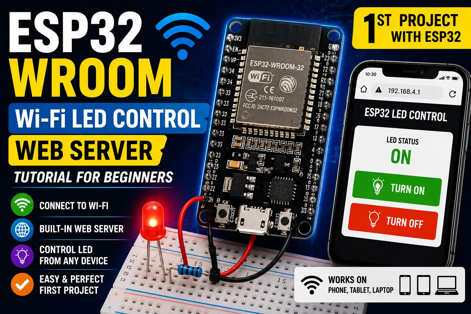
Connect: LED anode → 330 Ω → GPIO 26, LED cathode → GND.
GPIO 26 is a clean output pin with no boot-mode implications and is clearly labelled on most dev board silkscreen labels.
Uploading to ESP32
Unlike the Uno, some ESP32 dev boards require you to hold the BOOT button while the IDE starts transmitting, then release it. Boards with the CP2102 chip usually auto-reset; boards with CH340 often need the manual button press.
If upload fails with A fatal error occurred: Failed to connect to ESP32, try:
- Hold the BOOT button before clicking Upload
- Release BOOT once you see
Connecting....in the IDE console - If that still fails, check that your cable has data lines (charge-only cables are common and useless for programming)
After a successful upload, press the EN (enable/reset) button to restart the board and run the new firmware.
Steps
- 1Add Espressif board manager URL in IDE Preferences and install the esp32 package
- 2Select board: ESP32 Dev Module, upload speed 921600
- 3Install CH340 driver if the COM port does not appear after plugging in
- 4Wire LED through 330Ω to GPIO 26, cathode to GND
- 5Click Upload — hold BOOT button if connection fails, release on 'Connecting...'
- 6After upload completes, press EN to reset — LED should start blinking
- 7Open Serial Monitor at 115200 baud to see chip info and LED state messages