

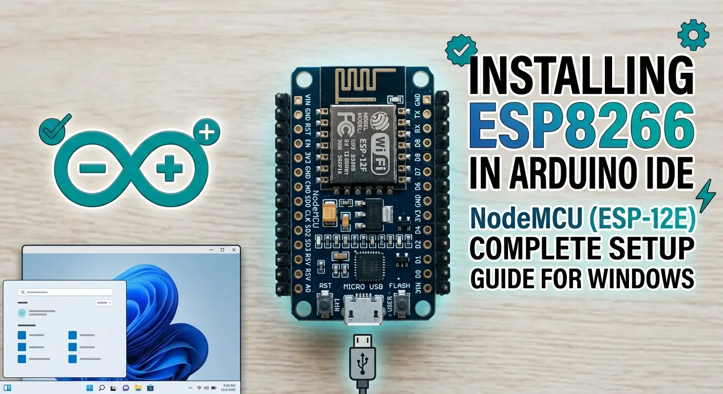
If you just unboxed a NodeMCU board and plugged it into your laptop expecting Arduino IDE to magically recognize it — bad news, it doesn't. The ESP8266 isn't an official Arduino chip, so the IDE has zero idea what to do with it out of the box. You need to feed it a board package first, then a driver, then actually tell it which COM port your board showed up on. Miss any one of these three things and you'll be staring at a red error bar wondering what you did wrong.
I've set this up on more machines than I can count at this point — for my own boards, for the tutorials on this site, for a couple of friends who bought their first NodeMCU off Amazon and had no clue where to start. The steps themselves are simple, but there's always one small thing that trips people up (usually the driver, sometimes the URL, occasionally a cable that only does power and not data — yes, that's a real thing, and yes it will waste twenty minutes of your life before you realize it).
This guide walks through the whole thing start to finish on Windows, since that's what most of you are running, with the NodeMCU ESP-12E as the main board since it's the one almost everyone starts with. Mac gets a shorter section near the end since the process barely changes, and the bare ESP-01 module gets a quick note too since it needs a slightly different upload setup.
What You'll Need
Before touching any software, make sure you actually have the hardware sorted:
- A NodeMCU ESP-12E development board (this is the one with the built-in USB-to-serial chip and USB port — not the bare ESP-01 module)
- A micro USB cable that supports data transfer, not just charging. This is the single most common reason people get stuck at "board not detected" and don't realize it. If your cable came bundled with a power bank or a cheap USB fan, it's suspect.
- Arduino IDE installed on your computer. Grab it from arduino.cc/en/software if you haven't already — either the classic 1.8.x or the newer 2.x IDE works fine for everything in this guide, the menu names are nearly identical.
That's genuinely it for hardware. No breadboard needed for this part — we're just getting the IDE to talk to the board and blink the onboard LED.
Step 1: Install Arduino IDE
Download the Windows installer from the official Arduino site and run through the setup wizard — Next, Next, Install, the usual. When it asks about driver installation for other Arduino boards (Uno, Mega, etc.), just accept it; doesn't hurt to have those too.
Once it's installed, open it up once just to confirm it launches properly before moving on. If you already have Arduino IDE installed from an old project, it's worth checking you're on a reasonably recent version — very old 1.6.x era installs sometimes choke on newer ESP8266 core versions.
Step 2: Install the USB-to-Serial Driver (Windows)
This is the step everyone forgets exists, because on official Arduino boards Windows just handles it silently. NodeMCU boards don't have an FTDI chip like genuine Arduinos — they use either a CP2102 or a CH340/CH341 USB-to-serial chip, depending on which manufacturer's clone you bought. Both are extremely common; neither is "better," they're just different chips that both do the same job.
Here's the thing — you can actually skip figuring out which one you have and just check first. Plug your NodeMCU into your laptop, open Device Manager (right-click Start menu → Device Manager), and expand Ports (COM & LPT).
- If you see something like Silicon Labs CP210x USB to UART Bridge (COMx) — driver's already there, skip to Step 3.
- If you see USB-SERIAL CH340 (COMx) — also already there, skip to Step 3.
- If instead you see a yellow warning triangle next to an "Unknown Device," or nothing shows up under Ports at all — you need to install the driver manually.
For the CP2102, grab the driver from Silicon Labs directly: silabs.com/developers/usb-to-uart-bridge-vcp-drivers
For the CH340/CH341, the most reliable source is the manufacturer's page, since a lot of the mirror download sites are sketchy: Search "CH340 driver Windows" and grab it from a WCH-affiliated or well-known electronics distributor page — avoid random .exe files from forum posts.
Run the installer, let it finish, unplug and replug your NodeMCU, and check Device Manager again. You should now see a proper COM port assigned. Note down the number (COM3, COM7, whatever it is) — you'll need it in a bit.
A small but annoying gotcha: some cheap NodeMCU clones ship with a slightly older CH340 chip revision that Windows 10/11 flags as an unsigned driver. If your driver install seems to succeed but the port still doesn't show up, you may need to disable Windows driver signature enforcement temporarily. There's a proper guide for that linked in the troubleshooting section below — don't disable Secure Boot or anything drastic, this is a much smaller, temporary setting.
Step 3: Add the ESP8266 Boards Manager URL
Now for the part that actually tells Arduino IDE that ESP8266 boards exist at all. Open Arduino IDE and go to:
File → Preferences (on the newer Arduino IDE 2.x it's the same menu, sometimes labeled Settings)
In the Preferences window, find the field labeled "Additional Boards Manager URLs". Paste this in:
https://arduino.esp8266.com/stable/package_esp8266com_index.json
Quick note if you're also working with ESP32 boards on the same machine — you don't need two separate preference entries. Just separate the URLs with a comma in the same field:
https://espressif.github.io/arduino-esp32/package_esp32_index.json,https://arduino.esp8266.com/stable/package_esp8266com_index.json
Click OK to save and close the Preferences window.
If you get "Error downloading package_esp8266com_index.json": this usually isn't your fault. It's either a network/firewall issue, or (less commonly) your antivirus intercepting the download. Double-check you copied the URL exactly — no trailing spaces, and it should be https, not http, since the old http version of this URL has caused download errors for a lot of people recently. If it still fails, try switching networks (mobile hotspot is a quick test) or temporarily pausing antivirus/VPN.
Step 4: Install the ESP8266 Board Package
With the URL saved, go to:
Tools → Board → Boards Manager…
In the search box that pops up, type esp8266. You should see an entry called "esp8266 by ESP8266 Community". Click on it, and an Install button will appear — click that.
This download is a few hundred MB since it includes the full toolchain (compiler, linker, the works), so depending on your connection this can take anywhere from thirty seconds to a few minutes. Don't close the IDE while it's installing.
Once it finishes, you'll see "INSTALLED" next to the package. That's it — the IDE now understands ESP8266 boards.
Step 5: Select Your Board and Port
Close the Boards Manager window and go back to:
Tools → Board → esp8266 → NodeMCU 1.0 (ESP-12E Module)
This is the entry you want for a standard NodeMCU dev board. Don't overthink the other similarly-named options in that list (Generic ESP8266 Module, NodeMCU 0.9, WeMos D1 Mini, etc.) — unless you specifically know you're holding one of those, "NodeMCU 1.0 (ESP-12E Module)" is correct for the typical NodeMCU dev kit.
Now set the port. Go to Tools → Port and select the COM port your board showed up as back in Step 2.
If you don't see any COM port listed here at all, stop and go back to Step 2 — the driver isn't installed correctly, or your cable is power-only. This is the number one reason people get stuck at this exact point.
While you're in the Tools menu, it's worth leaving the rest of the board settings (Upload Speed, CPU Frequency, Flash Size) at their defaults for now. 115200 baud upload speed and 4MB flash size work fine for a first test. You can tune these later once you're comfortable.
Step 6: Upload a Test Sketch
Time to actually confirm everything works. Paste this into a new sketch:
// solderhub.com blink led.

// the setup function runs once when you press reset or power the board
void setup() {
  // initialize digital pin LED_BUILTIN as an output.
  pinMode(LED_BUILTIN, OUTPUT);
}

// the loop function runs over and over again forever
void loop() {
  digitalWrite(LED_BUILTIN, HIGH);  // change state of the LED by setting the pin to the HIGH voltage level
  delay(1000);                      // wait for a second
  digitalWrite(LED_BUILTIN, LOW);   // change state of the LED by setting the pin to the LOW voltage level
  delay(1000);                      // wait for a second
}
A quick note before you upload: on most NodeMCU ESP-12E boards, the onboard blue LED is wired active-LOW, meaning LOW turns it on and HIGH turns it off — backwards from what you'd expect. Don't worry if your LED behavior looks "inverted" compared to what you assumed; that's normal, not a bug in your code.
Click Upload (the arrow icon, top left).
Unlike a bare ESP-01, the NodeMCU dev board has automatic reset circuitry built in, so you don't need to hold any buttons to get it into flashing mode — it should just work. Watch the bottom console; you'll see it compile, then a bunch of dots while it connects, then "Hard resetting via RTS pin" once the upload finishes. That message is normal and means it worked — the IDE isn't stuck, it's just telling you the board reset itself back into run mode.
Your onboard LED should now be blinking every second. If it is — you're done, your dev environment is fully working, and you can move on to anything else on this site that uses the ESP8266.
For Mac Users
The whole process above is basically identical on macOS — same Preferences window (Arduino → Preferences instead of File → Preferences on Mac), same boards manager URL, same Boards Manager install steps.
The one real difference is drivers. Modern macOS versions include CP2102 (Silicon Labs) driver support natively for most versions, so plenty of NodeMCU boards will just show up under Tools → Port as something like /dev/cu.SLAB_USBtoUART without you installing anything. If yours doesn't show up, grab the Mac driver from the same Silicon Labs page linked above, or the CH340 Mac driver if Device Manager (Mac's equivalent being System Information → USB) shows a CH340 chip instead. After installing, you may need to allow the driver under System Settings → Privacy & Security, since Apple blocks unsigned kernel extensions by default — there's usually an "Allow" button that appears right after a failed driver load attempt.
Everything else — board selection, port selection, uploading, the LED behavior — is exactly the same as Windows.
Working with the ESP8266-01 (ESP-01)
If what you've got is the tiny black ESP-01 module rather than a full NodeMCU dev board, the software side is the same (same boards manager URL, same board package), but the physical upload process is different, since the ESP-01 has no onboard USB port or auto-reset circuitry.
You'll need an FTDI programmer (or any USB-to-serial adapter set to 3.3V logic) wired up like this:
| ESP-01 Pin | FTDI Programmer |
|---|---|
| TX | RX |
| RX | TX |
| CH_PD (EN) | 3.3V |
| GPIO0 | GND (only while uploading) |
| VCC | 3.3V |
| GND | GND |
Grounding GPIO0 puts the ESP-01 into flashing mode. Once your upload is done, disconnect GPIO0 from GND and power-cycle the module (unplug/replug or press reset if your breakout board has one) to run the sketch normally.
Board selection in this case is Tools → Board → esp8266 → Generic ESP8266 Module, and set Flash Size to match your specific module (most ESP-01 boards are 1MB, though some newer ESP-01S variants use 1MB with different layouts — check the silkscreen or seller listing if unsure).
One more thing worth knowing about the ESP-01: it draws a brief current spike during Wi-Fi transmission that a lot of USB ports and FTDI adapters simply can't supply cleanly, which shows up as random resets or failed connections that look like a software problem but aren't. If you're seeing that, a separate 3.3V supply with a decent capacitor across it solves it more often than any code change does.
Troubleshooting
"Failed to connect to ESP8266: Timed out waiting for packet header" On a NodeMCU dev board, this is rare since auto-reset handles flash mode for you — if you see it, try a different USB cable first, then a different USB port on your computer (avoid USB hubs, plug directly into the laptop). On an ESP-01 without auto-reset circuitry, this almost always means GPIO0 isn't grounded during the upload attempt.
Port not showing up under Tools → Port at all Go back to Step 2. Either the driver isn't installed, or it installed for the wrong chip (check Device Manager again after driver install). Also worth trying a different cable — I've genuinely lost count of how many "broken NodeMCU" reports turned out to be a charge-only cable.
Upload starts but fails partway through Usually a power issue rather than a software one. If you're powering the NodeMCU through a long or thin USB cable, or through a USB hub, try plugging directly into a laptop's USB port with a short, decent-quality cable.
Sketch uploads fine but nothing happens Double check you selected the right board entry (NodeMCU 1.0 ESP-12E Module, not Generic ESP8266 Module) and that you're looking at the correct LED — some clone boards use GPIO16 or a different pin for the onboard LED instead of GPIO2. If your LED just doesn't blink, try flipping the HIGH/LOW logic in the code, since board LED polarity does vary between manufacturers.
Windows won't accept the CH340 driver, says it's unsigned This is a known Windows 10/11 issue with older CH340 driver versions. Search for "CH340 driver Windows 11 unsigned fix" — there are updated signed driver packages from WCH that resolve this without touching Secure Boot settings.
A Note on the Other Tools Menu Settings
Once the blink test works, you'll probably poke around the rest of the Tools menu and wonder what the other options actually do. Quick rundown, since these come up in almost every ESP8266 project on this site:
- Upload Speed — this is just the baud rate used during flashing, not how fast your code runs afterward. 115200 is the safe default and works on basically every cable and board combo. Bumping it to 230400 or 460800 can speed up uploads on a good USB connection, but if you start seeing sync errors, drop it back down.
- CPU Frequency — 80 MHz vs 160 MHz. Leave it at 80 MHz unless you're doing something CPU-heavy (image processing on an OLED, certain crypto-heavy TLS connections). Higher frequency draws more power and doesn't help the vast majority of hobby projects.
- Flash Size — this needs to roughly match your board's actual flash chip, since it affects how much space is reserved for SPIFFS/LittleFS storage versus your sketch. Most NodeMCU ESP-12E boards ship with 4MB flash, so "4MB (FS:2MB OTA:~1019KB)" or similar is a safe starting option. Wrong flash size settings don't usually break a simple blink sketch, but they'll bite you later if you try to read or write files to the board's internal storage.
- Erase Flash — leave this on "Only Sketch" for normal use. "All Flash Contents" wipes everything including any saved Wi-Fi credentials or stored files, which is occasionally useful for a genuinely fresh start but not something you want by default.
None of these need to be touched for the blink test above — just useful to know they exist before you start following other tutorials that mention changing one of them.
Quick FAQ
Do I need to install ESP8266 board support separately for every new project? No. This is a one-time IDE setup. Once installed, it stays installed across every sketch and every project you open afterward, on that same computer.
My board worked yesterday, today the port is gone. What happened? Nine times out of ten this is a cable or USB port going flaky, not the board or the software. Try a different USB port on your PC first, then a different cable, before assuming the board itself is damaged.
Can I use the same setup for ESP32 boards too? Yes, and you don't need to redo anything — just add the ESP32 boards manager URL alongside the ESP8266 one in the same comma-separated field from Step 3, then install the ESP32 package the same way through Boards Manager.
Is NodeMCU 1.0 (ESP-12E Module) the same as "NodeMCU 12E" written on the box? Yes, same thing. Board manufacturers aren't consistent with naming on the packaging, but if your board has the USB port, roughly a dozen GPIO pins broken out, and says anything with "NodeMCU" and "12E" or "V2/V3" on it, this is the correct board entry.
Conclusion
Once you've got this working, you will basically got it working forever — this is a one-time setup per computer, not per project. Every future ESP8266 sketch, whether it's a simple sensor read or a full web server, starts from exactly this same point: board selected, port selected, hit upload.
If your NodeMCU is blinking away happily right now, you're all set to move on to actually building something with it.