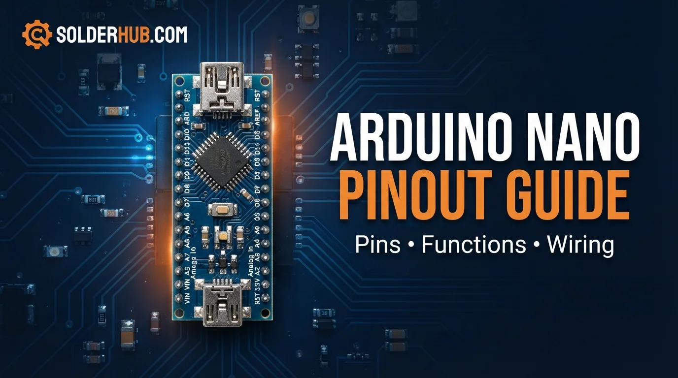
If you have ever built a circuit on a breadboard and then wanted to make it permanent, you have probably met the Arduino Nano. It is the Uno's brain on a board about the size of a stick of gum, 45 × 18 mm, with two rows of pins that drop straight into a breadboard or solder into a project box.
The catch is that everything got smaller. The silkscreen labels are tiny, the pins sit close together, and a few details differ from the Uno enough to trip you up if the bigger board is all you have used. The Nano has two extra analog inputs, no barrel jack, no separate SDA and SCL pins, and a USB-to-serial chip that has opinions about anything you wire to D0 and D1.
This guide walks through the board pin by pin, using Arduino's official pinout as the reference: power, digital, PWM, interrupts, serial, SPI, I2C and analog, followed by a complete pin table to keep open while you wire. Wherever the Nano behaves differently from the Uno, it is called out.
What's Actually on the Board
The Nano is built around the same ATmega328P as the Uno: an 8-bit AVR core at 16 MHz with 32 KB of flash (about 0.5 KB used by the bootloader, or 2 KB on older bootloaders), 2 KB of SRAM and 1 KB of EEPROM. Logic runs at 5 V, and power comes from the Mini-B USB port, the VIN pin or the 5V pin.
The header has 30 pins in two rows of 15: 14 digital I/O pins (D0–D13), 8 analog inputs (A0–A7), and a small group of power and control pins. The chip on the board is the surface-mount (TQFP) package of the ATmega328P, and that package is the reason the Nano has two more analog inputs than the Uno, whose 28-pin DIP chip does not expose them.
Boards use one of two USB-to-serial chips. Official Nanos use an FTDI FT232RL, which works without extra drivers on modern systems. Many clones use a CH340, which can need a driver on Windows and older macOS releases. If a Nano does not appear as a COM port, identifying that chip is the first thing to check.
Three Names for Every Pin
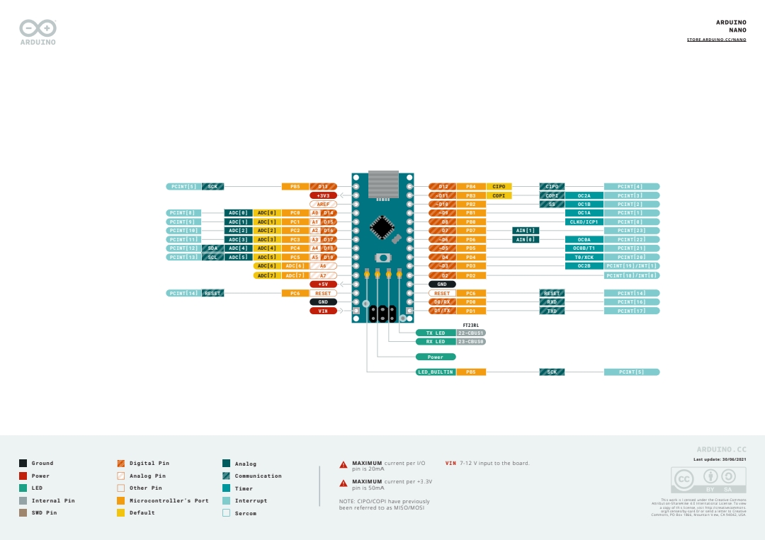
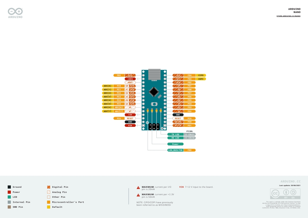
Arduino's diagram labels most pins with up to three names. The Arduino name (D13, A4) is what you use in sketches. The port name (PB5, PC4) is the ATmega328P's own label, which matters when you read the datasheet or write register-level code. The function names (SCK, SDA, OC1A, PCINT5) describe what the pin's built-in peripherals can do. The complete pin table later in this guide maps all three.
Power Pins
| Pin | Description |
|---|---|
| VIN | Input to the onboard regulator, 7–12 V |
| 5V | Regulated 5 V. An output when powered from USB or VIN, an input if you bypass the regulator |
| 3V3 | 3.3 V output, 50 mA maximum |
| GND | Ground (two on the headers, one more on the ICSP header) |
| RESET | Pull LOW to reset the ATmega328P (two pins on the headers, wired together) |
| AREF | Reference voltage for the ADC |
VIN is not the same as 5V. Voltage on VIN passes through the onboard linear regulator, which steps it down to 5 V. Connecting an external supply straight to the 5V pin skips the regulator entirely, and anything much above 5 V there can destroy the board. Arduino's pinout specifies 7–12 V for VIN. A linear regulator turns the difference into heat, so the higher the input and the more current you draw, the warmer it gets.
There is no barrel jack. Unlike the Uno, the Nano takes power only from the USB port, VIN or the 5V pin. For a battery-powered build, a 9 V supply on VIN is the usual choice.
The 3V3 pin is small. Arduino lists 50 mA as the maximum. On the official board that rail comes from the FT232RL, and clones vary. It is fine for a single low-power sensor, but a radio module or anything that draws more needs its own 3.3 V regulator.
On USB power, the port sets the limit. A USB port typically supplies around 500 mA, and the board itself uses part of that before your peripherals draw anything from the 5V pin.
Digital I/O Pins (D0–D13)
Fourteen general-purpose pins, each configured as an input or output with pinMode() and switching between 0 V and 5 V. Arduino's pinout lists 20 mA as the maximum per pin. The ATmega328P datasheet gives 40 mA as the absolute limit, but 20 mA is the number to design around.
D13 also drives the onboard "L" LED (LED_BUILTIN) through a series resistor. That makes it a handy heartbeat indicator, but the LED loads the pin: if you use D13 as an input with the internal pull-up enabled, the LED drags the reading down and the value can be unreliable. Use a different pin for inputs when you can.
PWM Pins (~3, ~5, ~6, ~9, ~10, ~11)
Six pins carry a tilde on the silkscreen and can produce PWM with analogWrite(). PWM switches a pin on and off rapidly, and the duty cycle sets the effective level seen by an LED or motor. Each PWM pin is tied to one of the chip's three timers:
| Pin | Timer output | Timer | Frequency |
|---|---|---|---|
| D3 | OC2B | Timer2 | ~490 Hz |
| D5 | OC0B | Timer0 | ~980 Hz |
| D6 | OC0A | Timer0 | ~980 Hz |
| D9 | OC1A | Timer1 | ~490 Hz |
| D10 | OC1B | Timer1 | ~490 Hz |
| D11 | OC2A | Timer2 | ~490 Hz |
The frequency split is invisible when dimming an LED, but it matters for motor drivers and audio. The shared timers also explain a class of library conflicts. The Servo library uses Timer1, so PWM on D9 and D10 stops working while it is active. tone() uses Timer2, which takes over D3 and D11. Timer0 also runs millis() and delay(), so changing its settings to alter D5 or D6 changes your timing too.
External and Pin Change Interrupts
Only D2 (INT0) and D3 (INT1) support attachInterrupt(), so they are the pins to reserve for rotary encoders, tachometers and flow-sensor pulses.
Every other digital pin, plus A0–A5, supports pin change interrupts instead. They are grouped by port: PCINT0–7 on D8–D13, PCINT8–13 on A0–A5, and PCINT16–23 on D0–D7. Each group shares one interrupt vector, so your handler has to work out which pin actually changed. Libraries such as EnableInterrupt or PinChangeInterrupt hide that bookkeeping. A6 and A7 have no pin change interrupt at all.
UART, USB and the Onboard LEDs
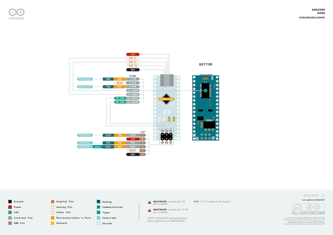
The Nano has one hardware UART, on D0 (RX) and D1 (TX), shared with the USB-to-serial chip that handles uploads and the Serial Monitor.
| Pin | Function |
|---|---|
| D0 | RX (wired to the USB chip's TXD) |
| D1 | TX (wired to the USB chip's RXD) |
That shared line has three practical consequences:
- Peripherals on D0 and D1 can block uploads. A GPS or Bluetooth module wired there competes with the USB chip, and uploads often fail with a sync error until you unplug it.
- Opening the Serial Monitor resets the board. The USB chip's DTR line is coupled to RESET, which is how the IDE resets the board before an upload. Opening a serial port toggles DTR the same way, so
setup()runs again each time. - A second serial port has to be software.
SoftwareSerialon two spare pins works for low speeds, but it is CPU-intensive and unreliable at higher baud rates.
The board carries four LEDs. TX and RX are driven by the USB chip and blink on serial traffic and uploads. PWR stays on whenever the board is powered. L is the D13 LED described above.
If uploads fail with an avrdude stk500_getsync() "not in sync" error and nothing is wired to D0 or D1, choose Processor: ATmega328P (Old Bootloader) in the Tools menu. Many clones ship with the older bootloader.
SPI Pins and the ICSP Header
SPI is the protocol for fast peripherals such as SD cards, TFT displays and radio modules.
| Pin | Function | Port |
|---|---|---|
| D10 | SS (chip select) | PB2 |
| D11 | COPI (formerly MOSI) | PB3 |
| D12 | CIPO (formerly MISO) | PB4 |
| D13 | SCK (clock) | PB5 |
Arduino's current documentation uses COPI and CIPO for what older tutorials and libraries call MOSI and MISO. The pins are the same.
That pinMode(10, OUTPUT) line matters. If D10 is configured as an input and something pulls it low, the ATmega328P can drop out of master mode, and SPI communication fails in confusing ways. Set it as an output even if your real chip-select line is on another pin.
The same signals also appear on the 2×3 ICSP header: pin 1 CIPO, pin 2 +5V, pin 3 SCK, pin 4 COPI, pin 5 RESET and pin 6 GND. You use it to burn a bootloader or to program the chip with an external ISP programmer, bypassing the USB chip completely. Because D13 is both SCK and the L LED, that LED flickers during SPI traffic. That is normal.
I2C Pins (A4 and A5)
I2C connects a chain of devices over two wires, and it is the protocol behind most OLED displays, real-time clocks and IMU breakouts.
| Pin | Function | Port |
|---|---|---|
| A4 | SDA (data) | PC4 |
| A5 | SCL (clock) | PC5 |
The Nano has no dedicated SDA and SCL pins beside AREF, the way the Uno R3 does. A4 and A5 are the only I2C pins, so using them for I2C means they are no longer available as analog inputs. Most breakout boards include their own pull-up resistors. Bare I2C chips need external pull-ups, typically 4.7 kΩ on both lines, because the ATmega328P's internal pull-ups (roughly 20–50 kΩ) are too weak for long wires or faster buses. If a device is 3.3 V only and the bus is pulled up to 5 V, you need a level shifter.
Analog Input Pins (A0–A7)
All eight analog pins feed the same 10-bit ADC, which returns values from 0 to 1023 across a 0–5 V range.
Each step is about 4.9 mV, and one conversion takes roughly 100 µs at the default settings, which is irrelevant for one sensor but adds up when you poll several inputs in a tight loop.
A0–A5 are flexible. They map to D14–D19, so they can be used as ordinary digital pins with pinMode() and digitalWrite() when you run short of numbered pins, and A4/A5 double as the I2C bus.
A6 and A7 are analog-input only. These are the two extra channels the TQFP package exposes, and on the chip itself they have no digital circuitry. You cannot use pinMode() or digitalWrite() on them, they have no internal pull-up, and they have no pin change interrupt. Plan them as spare sensor inputs, not as spare digital pins. A floating analog input reads noise, so tie an input to a real sensor or a known level before trusting the value.
AREF
AREF sets the ADC's reference voltage. By default the ADC measures against the 5 V supply. If a sensor only outputs 0–2.5 V, that wastes half your resolution, and feeding 2.5 V into AREF spreads the full 10 bits across the range you actually use.
Set the reference in code before you connect a voltage to AREF. Otherwise the internal reference and your external source end up fighting each other, and that can damage the chip. There is also a built-in 1.1 V reference, selected with analogReference(INTERNAL), which is useful for low-voltage sensors and needs no external wiring.
Complete Pin Table (D0–D13, A0–A7)
With the USB connector at the top, the left header runs D13, 3V3, AREF, A0–A7, 5V, RESET, GND and VIN from top to bottom. The right header runs D12 down to D2, then GND, RESET, D0 and D1.
| Pin | Port | Functions | Interrupt |
|---|---|---|---|
| D0 (RX) | PD0 | UART RXD | PCINT16 |
| D1 (TX) | PD1 | UART TXD | PCINT17 |
| D2 | PD2 | Digital I/O | INT0, PCINT18 |
| D3 | PD3 | PWM (OC2B) | INT1, PCINT19 |
| D4 | PD4 | T0, XCK | PCINT20 |
| D5 | PD5 | PWM (OC0B), T1 | PCINT21 |
| D6 | PD6 | PWM (OC0A), AIN0 | PCINT22 |
| D7 | PD7 | AIN1 | PCINT23 |
| D8 | PB0 | CLKO, ICP1 | PCINT0 |
| D9 | PB1 | PWM (OC1A) | PCINT1 |
| D10 | PB2 | PWM (OC1B), SPI SS | PCINT2 |
| D11 | PB3 | PWM (OC2A), SPI COPI | PCINT3 |
| D12 | PB4 | SPI CIPO | PCINT4 |
| D13 | PB5 | SPI SCK, onboard LED | PCINT5 |
| A0 (D14) | PC0 | ADC0 | PCINT8 |
| A1 (D15) | PC1 | ADC1 | PCINT9 |
| A2 (D16) | PC2 | ADC2 | PCINT10 |
| A3 (D17) | PC3 | ADC3 | PCINT11 |
| A4 (D18) | PC4 | ADC4, I2C SDA | PCINT12 |
| A5 (D19) | PC5 | ADC5, I2C SCL | PCINT13 |
| A6 | n/a | ADC6, analog input only | None |
| A7 | n/a | ADC7, analog input only | None |
AIN0 and AIN1 are the analog comparator inputs. T0, T1, XCK, CLKO and ICP1 are timer, counter and USART clock signals that most sketches never touch.
Practical Pin Usage Tips
Treat A6 and A7 as analog-only from the start. A plan that relies on using them as extra digital pins when you run out will not work on this board.
Keep D10 an output when using hardware SPI as master, even if your chip-select line is elsewhere.
Reserve D2 and D3 for anything time-critical. Pin change interrupts work on the other pins, but they take more code to set up and more time to sort out which pin fired.
Check timer conflicts before choosing PWM pins. If your project uses the Servo library, avoid relying on PWM at D9 and D10. If it uses tone(), avoid D3 and D11.
Budget total current, not just per-pin current. Each pin is good for 20 mA by design, but the chip as a whole has a combined limit of about 200 mA across its supply pins. Several LEDs driven without resistors can overheat it even if no single pin looks overloaded.
Keep D0 and D1 clear while uploading. Move anything connected there to a SoftwareSerial pair, or disconnect it during upload.
Common Mistakes and How to Avoid Them
Treating A6 and A7 like A0–A5. They read analog values only. No digital mode, no pull-up, no pin change interrupt.
Feeding an external supply into the 5V pin. This bypasses the regulator. Use VIN for anything above 5 V.
Connecting 3.3 V-only modules to 5 V pins. The Nano is a 5 V board. Many newer sensors and radios are not 5 V tolerant, and a level shifter is cheap insurance.
Powering motors, servos or LED strips from the board. USB power tops out near 500 mA, and the 3V3 pin gives 50 mA. Give high-current loads their own supply and connect the grounds together.
Skipping flyback diodes on inductive loads. Relays and solenoids generate a voltage spike when they switch off, and without a diode across the coil that spike can damage the driving pin.
Summary: Nano Pin Reference at a Glance
| Feature | Count / Detail |
|---|---|
| Header pins | 30 (two rows of 15) |
| Digital I/O | 14 (D0–D13) |
| PWM-capable pins | 6 (~3, ~5, ~6, ~9, ~10, ~11) |
| Analog inputs | 8 (A0–A7), of which A6 and A7 are analog-only |
| External interrupts | 2 (D2, D3) |
| Pin change interrupts | 20 (D0–D13 and A0–A5) |
| Hardware UART | 1 (D0, D1) |
| SPI | D10–D13, also on the ICSP header |
| I2C | A4 (SDA), A5 (SCL) |
| ADC resolution | 10-bit |
| Flash / SRAM / EEPROM | 32 KB / 2 KB / 1 KB |
| Clock speed | 16 MHz |
| Logic level | 5 V |
| VIN range | 7–12 V |
| Max current per I/O pin | 20 mA (design limit) |
| 3V3 pin | 50 mA maximum |
| USB connector | Mini-B |
The Nano's appeal is not that it does anything the Uno cannot. It does nearly everything the Uno does in a footprint that drops onto a breadboard or solders into a project box. Once the A6/A7 rule and the D10 rule are habits, moving between Uno and Nano projects takes very little adjustment.
Arduino Nano · ATmega328P · 14 Digital Pins · 8 Analog Inputs (2 analog-only) · 1x UART · SPI · I2C · PWM
Quick Answers to Common Nano Pin Questions
How many pins does the Arduino Nano have? Thirty header pins: 14 digital (D0–D13), 8 analog (A0–A7), plus VIN, 5V, 3V3, GND, RESET and AREF.
Why does the Nano have 8 analog pins when the Uno has 6? The Nano uses the surface-mount package of the ATmega328P, which exposes two extra ADC channels, A6 and A7. They are analog-input only.
Which pins support PWM? D3, D5, D6, D9, D10 and D11, using analogWrite().
Can A0–A5 be used as digital pins? Yes, they map to D14–D19. A6 and A7 cannot.
Why does my Nano reset when I open the Serial Monitor? The USB chip's DTR line is connected to RESET. Opening the port toggles it, and the sketch restarts.
Which USB driver does my Nano need? It depends on the USB-to-serial chip. CH340 boards need the CH340 driver on some systems, and FTDI boards usually work without one.
Is the Nano's chip the same as the Uno's? It is the same ATmega328P silicon in a surface-mount package, with the same clock, memory and instruction set. Sketches move between them unchanged as long as they stay off pins one board does not have.
What about the Nano Every, Nano 33 IoT and Nano ESP32? They share the physical footprint but change the microcontroller. The Every uses an ATmega4809 and keeps 5 V logic. The 33 IoT uses a SAMD21 with WiFi and Bluetooth at 3.3 V. The Nano ESP32 uses an ESP32-S3, also at 3.3 V. Check logic levels before reusing wiring from a classic Nano.
Where to Go From Here
If the Nano's pin map now feels familiar, the Arduino Uno R3 pinout guide covers the bigger board built on the same chip, and the Arduino Mega 2560 pinout guide is the next step when you run out of pins. To see what changed in the newer Uno generation, read the Arduino Uno R3 vs R4 comparison. For projects that need wireless or more memory, the ESP32 pinout guide is the natural jump.