

Electrical / Current
Interfacing ACS712 Electrical / Current with Arduino Uno
What is the ACS712?
The ACS712 is a Hall-effect current sensor that measures AC or DC current without placing the microcontroller directly in the measured current path. Current flows through the module’s heavy-current terminals (IP+ and IP−); the sensor produces an analog voltage on OUT that changes with the magnetic field created by that current. On a typical 5 V module, the output sits near 2.5 V at zero current and moves up or down as current direction and magnitude change.
The practical details matter more than the basic hookup: choose the correct ±5 A, ±20 A or ±30 A variant, calibrate the zero-current voltage, and protect 3.3 V microcontroller ADC inputs from an output that can exceed 3.3 V.
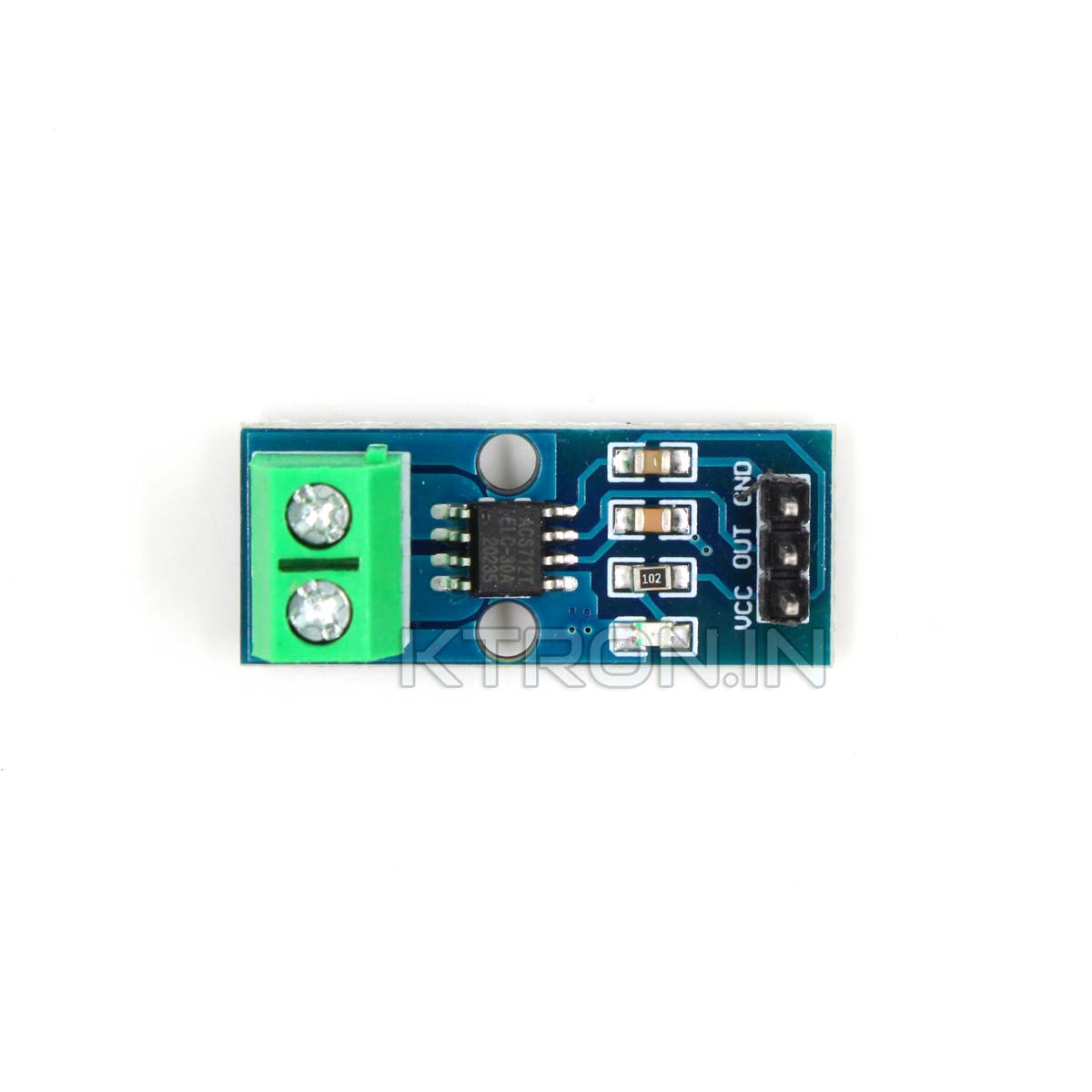
ACS712 at a glance
- Sensor supply
- 5 V DC for the ACS712 IC; breakout input details can vary
- Measurement
- AC and DC current, measured in series through IP+ / IP−
- Output
- Analog voltage; approximately VCC/2 at zero current
- Current variants
- ±5 A, ±20 A or ±30 A
- Typical sensitivity
- 185 mV/A (±5 A), 100 mV/A (±20 A), 66 mV/A (±30 A)
- Microcontroller interface
- Analog ADC input; no digital protocol or sensor library required
- Internal conductor resistance
- About 1.2 mΩ typical for the IC
- Bandwidth
- Up to 80 kHz typical; practical bandwidth depends on filtering and module design
Choose the correct ACS712 variant
| Variant | Current range | Typical sensitivity | Trade-off |
|---|---|---|---|
| ACS712-05B | −5 A to +5 A | 185 mV/A | Best signal change per amp; smallest range |
| ACS712-20A | −20 A to +20 A | 100 mV/A | Middle range for many DC loads |
| ACS712-30A | −30 A to +30 A | 66 mV/A | Widest range, lower resolution per amp |
Swipe sideways to see every column →
Module pins and current terminals
- VCC
- Power the module from its specified 5 V supply.
- GND
- Signal ground. Connect to the microcontroller ground.
- OUT
- Analog voltage output; connect to an ADC input only after checking the ADC voltage limit.
- IP+
- One end of the high-current path. Put this path in series with the source and load.
- IP−
- The other end of the high-current path. Current flowing IP+ to IP− makes OUT rise above its zero-current level.
How the ACS712 measures current
The measured current flows through a low-resistance copper conductor inside the IC. Its magnetic field is sensed by a Hall element, which produces a proportional analog voltage on OUT. The high-current conductor and signal pins are galvanically isolated inside the IC, but the safety of a finished module also depends on its PCB layout, terminal spacing, insulation and workmanship.
At zero current, OUT is nominally half the supply voltage (about 2.5 V with a 5 V supply). Current in one direction raises the output; reversing the current lowers it. The output is not a digital ampere value: the microcontroller must sample the voltage and calculate current using the sensitivity of the exact variant.
Calculate current from the output voltage
For a 5 V supply, use the following as a starting model:
Current (A) = (VOUT − VZERO) / sensitivity (V/A)
| Variant | Sensitivity for the formula |
|---|---|
| ACS712-05B | 0.185 V/A |
| ACS712-20A | 0.100 V/A |
| ACS712-30A | 0.066 V/A |
VZERO should be measured on your actual module with no current flowing. Do not assume it is exactly 2.500 V: offset, supply voltage, ADC reference and noise all affect the result. Averaging several samples at zero current improves the baseline. These values are typical datasheet sensitivities, not a substitute for calibration against a known current.
Warning
**Voltage and wiring safety:** IP+ and IP− are part of the measured current path and must be wired **in series** with the load, never in parallel across a supply. Disconnect power before changing this wiring and use terminals, wire gauge and fusing rated for the expected current. The ACS712 IC's internal isolation does not make an inexpensive breakout automatically safe for mains voltage. For mains measurements, use properly rated equipment and enclosure; do not handle exposed live wiring.
DC current versus AC current
For DC current, read OUT, convert the ADC reading to voltage, subtract the calibrated zero-current voltage and divide by the variant sensitivity. The sign indicates current direction; a small negative or fluctuating reading at zero current is usually offset and noise.
For AC current, the signal swings around its zero-current midpoint. Sampling only once per cycle or using the DC formula on one sample does not give AC RMS current. Sample fast enough to capture the waveform, remove the measured midpoint, calculate the root-mean-square of the samples and calibrate the result against a known AC current. The ADC sampling rate, analog filtering and waveform frequency determine usable accuracy.
Where it is useful
- DC load monitoring: measure current drawn by a battery-powered load within the selected module's range.
- Motor experiments: observe changes in motor current as load or speed changes.
- AC load measurement: sample the waveform and calculate RMS current in software.
- Overcurrent experiments: compare measured current with a threshold and trigger a warning or shutdown in the controller.
- Energy-monitoring prototypes: pair current measurements with a separately measured voltage if power is required.
The ACS712 measures current, not voltage or energy by itself. Accurate power measurement needs voltage measurement and suitable sampling/calibration as well.
Troubleshooting
| Symptom | Likely cause | What to check |
|---|---|---|
| Current is not near zero with no load current | Zero-current offset, noise or ADC scaling error | Measure OUT with no current flowing and update ZERO_CURRENT_V; average samples. |
| Current magnitude is wrong by a consistent factor | Wrong sensitivity constant or ADC reference | Confirm the 5 A / 20 A / 30 A variant and match the code to it. |
| Reading changes in the wrong direction | Current direction is reversed | Check whether current flows IP+ to IP−; reverse the high-current path if appropriate. |
| ESP32 readings clip or the board resets | OUT exceeds the ADC's permitted voltage or wiring is noisy | Add a correctly calculated voltage divider, share signal ground and keep wiring short. |
| AC reading is unstable or too low | Sampling too slowly, wrong RMS calculation or poor calibration | Sample the waveform at a suitable rate, remove the midpoint and calculate RMS. |
| Output is noisy near a motor | Switching noise and magnetic interference | Separate signal wiring from motor leads, use appropriate filtering and average samples. |
Frequently asked questions
Can the ACS712 measure both AC and DC? Yes. Its analog output changes with current in either direction. DC is calculated from the offset; AC current requires waveform sampling and an RMS calculation for an RMS value.
Does OUT read 0 V when no current flows? No. With a 5 V supply, it is nominally near 2.5 V. Calibrate the actual zero-current value on your module.
Can I connect OUT directly to an ESP32? Do not assume it is safe. The ACS712 is powered from 5 V and its output can exceed 3.3 V, depending on variant and current. Use a properly designed divider or suitable signal-conditioning stage so the full possible output remains within the ADC limits.
Which variant should I choose? Choose the lowest range that safely covers the expected peak current. The ±5 A variant has the highest sensitivity; the ±30 A variant covers more current but produces a smaller voltage change per amp.
Does it provide watts or energy directly? No. It measures current. Power requires voltage measurement too, and energy requires integrating power over time.
Is the module safe for mains? Do not judge safety by the IC's isolation rating alone. The complete board, terminals, spacing, enclosure and installation must be appropriately rated.
Continue with a board integration: ACS712 with Arduino Uno · ACS712 with ESP32
Setting Up ACS712 with Arduino Uno
Read DC current from an ACS712 module with an Arduino Uno. The sensor output is analog and sits near half the supply voltage at zero current. This example calibrates that zero-current baseline at startup, then reports current using the sensitivity of the selected 5 A, 20 A or 30 A variant.
ACS712 to Arduino Uno
| ACS712 pin | Uno connection | Important note |
|---|---|---|
| VCC | 5V | Use a stable 5 V supply within the module rating. |
| GND | GND | Share signal ground with the Uno. |
| OUT | A0 | Check that the complete output range is within the Uno ADC input range. |
| IP+ / IP− | In series with the load | Route the measured current through these terminals; never connect them in parallel across the supply. |
Swipe sideways to see every column →
Warning
**Wire the current path in series.** IP+ and IP− carry the load current; VCC, GND and OUT are the low-voltage signal side. Do not connect OUT to the Uno until you have confirmed the module output is within the ADC input range. Disconnect power before changing the current-path wiring.
- 1Disconnect power and wire VCC, GND and OUT to the Uno as shown.
- 2Put IP+ and IP− in series with the load's supply conductor, using terminals and wiring rated for the expected current.
- 3Ensure no current flows through IP+ / IP−, then power the sensor and Uno so startup calibration can capture the zero-current output.
- 4Select the correct SENSITIVITY constant for the exact ACS712 variant and upload the sketch.
- 5Open Serial Monitor at 115200 baud. Apply a known, safe DC load and compare the reading with a trusted meter.
- 6If the reading is biased, recalibrate the zero-current voltage and verify the actual ADC reference voltage.
Expected output
Serial Monitor prints the measured output voltage and calculated current every 250 ms. With zero current, the calculated value should be near 0 A but may fluctuate slightly because of ADC quantization, noise and offset. Recalibrate with no current flowing if the baseline is consistently shifted.
Troubleshooting
- Large current at idle: rerun zero-current calibration and confirm the load is truly off during startup.
- Wrong scale: check whether the module is ±5 A, ±20 A or ±30 A and change SENSITIVITY.
- Negative current: the current may be flowing IP− to IP+; the sign indicates direction.
- Noisy reading: average more samples, shorten signal wiring and separate it from motor leads.
- AC load: this sketch is for DC. Sample the waveform and calculate RMS for AC current.
Related Components

A3144
Digital Hall-effect switch for contactless magnetic detection
ADXL345
Low-power 3-axis accelerometer with tap/double-tap and freefall detection for wearables.
AHT10
A tiny I2C sensor that packs temperature and humidity sensing into the smallest footprint possible.
BH1750
I2C lux sensor that outputs calibrated light readings — no ADC or calibration required.
Related Guides & Projects
Arduino Uno R4 Minima Pinout: Every GPIO, ADC, DAC, and Op-Amp Pin Explained
A complete Arduino Uno R4 Minima pinout reference — digital I/O, ADC, DAC, op-amp, CAN, dual UART, and exactly what it leaves out compared to the WiFi variant.
Mastering PWM on Arduino: Dimming LEDs and Controlling Motors
Understand what PWM actually is on Arduino, dim an LED smoothly, and safely control a DC motor's speed with a driver chip -- plus the mistakes (like wiring a motor straight to a pin) that damage boards.
4-Digit 7-Segment Counter with TM1637 & Arduino
Drive a TM1637-based 4-digit 7-segment display with Arduino Uno to show a real-time up/down counter, elapsed timer, and scrolling text. Covers library setup, brightness control, and custom segment mapping.
Arduino Uno R4 Minima vs WiFi: Which One Should You Choose?
Same processor, same memory, different price. Here's what the WiFi variant's extra hardware actually gets you, and when the Minima is the smarter buy.