What You Will Build
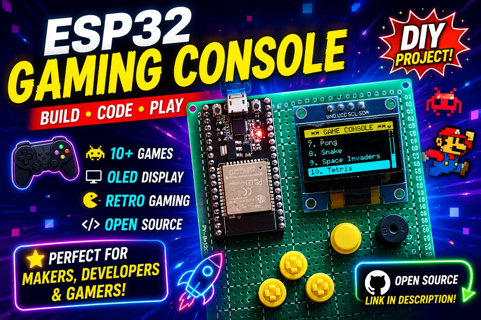
This project turns an ESP32 into a pocket-sized retro games console. A 0.96 inch 128×64 OLED is the screen, five tactile buttons form the controller, a small buzzer provides sound effects, and a menu lets you pick which game to run. The reference build runs eleven classics from one firmware image: Snake, Pong, Tetris, Breakout, Flappy Bird, Space Invaders, Asteroids, Pac-Man, Dino Run, Maze Runner and Tank. The parts cost under ten dollars and the whole thing fits on a piece of perfboard about the size of a credit card.
Rather than only describing the finished console, this guide gives you the engine that every game sits on, as complete, compile-ready code. It includes a debounced five-button input layer, a non-blocking sound system, a scrolling game menu, a fixed-rate game loop, a finished Snake game and an input-test screen for checking your wiring. Every other game then becomes a small, self-contained module that plugs into the same table. The full set of games is in the reference repository linked at the end.
Two engineering limits shape everything: a 128×64 monochrome screen that forces efficient drawing, and a shared RAM budget that every game has to live inside. Understanding both will make you a better embedded programmer long after this console is finished.
Components
11 itemsNeed these parts? Get this build sheet by email
Parts list with buy links, plus new builds as they're published. By subscribing you agree to our Privacy Policy. Unsubscribe anytime.
How the Pieces Fit Together
Four subsystems cooperate, and keeping them separate in code is what lets many games share one console.
| Subsystem | Hardware | What it provides to a game |
|---|---|---|
| Display | SSD1306 over I2C | A 1,024-byte frame buffer (128 × 64 ÷ 8) and drawing calls |
| Input | Five buttons on GPIO | A pressed flag for one frame per new press, and a held state |
| Audio | Passive buzzer on a PWM pin | A beep(frequency, duration) call that never blocks |
| Game loop | The ESP32 CPU | A fixed 30 frames per second tick that calls each game's update() and draw() |
The 30 fps figure is not arbitrary. An SSD1306 frame is 1,024 bytes, and at the 400 kHz I2C speed the Adafruit library uses during transfers, sending it takes roughly 25 to 30 ms once protocol overhead is counted. The display itself is therefore the bottleneck, and drawing faster than about 30 to 35 fps only wastes CPU. Faster I2C helps: many SSD1306 modules accept 1 MHz if you pass it to the display constructor, but 400 kHz is the safe default.
Each game is a module with the same four members: a name, an init() that resets its state, an update() that moves things and reads input, and a draw() that renders one frame. The menu and loop never need to know what a game does inside. They only call through a table of function pointers.
Step 1: Wire and Verify the OLED
The SSD1306 uses two I2C lines, whatever its resolution:
OLED VCC  → ESP32 3V3
OLED GND  → ESP32 GND
OLED SDA  → ESP32 GPIO 21
OLED SCL  → ESP32 GPIO 22
Before wiring anything else, flash a minimal I2C scanner and confirm the display responds. Most 128×64 modules answer at 0x3C, and a minority of clones use 0x3D. Getting this wrong is the most common failure in this build, so check it now, not after five buttons are soldered in.
Step 2: Wire the Buttons
Each button connects 3.3 V to a GPIO pin, with a 10 kΩ resistor from that same pin to GND. Pressed reads HIGH, released reads LOW, and all five buttons behave identically, which keeps the menu and every game on one input routine.
Button leg 1 → 3V3
Button leg 2 → GPIO pin (see table) AND → 10 kΩ resistor → GND
| Button | GPIO |
|---|---|
| Up | 13 |
| Down | 33 |
| Left | 14 |
| Right | 27 |
| Select | 26 |
A note on GPIO 12. Many builds, including the original reference design, put a button on GPIO 12. That pin is a strapping pin: the ESP32 reads it at reset to choose the flash voltage, and if it is HIGH on a 3.3 V flash module the board can fail to boot. A button on it works until someone holds it while pressing reset. GPIO 33 has no such duty, so this guide uses it for Down. If you flash the reference firmware instead of the code below, check which pins it defines.
The ESP32 can also provide pull-downs internally with pinMode(pin, INPUT_PULLDOWN), which would save the five resistors. We keep external ones because they are stronger and make the circuit independent of firmware.
Step 3: Wire the Buzzer and Install Libraries
Buzzer +  → GPIO 25
Buzzer −  → GND
Any ESP32 output pin can generate PWM through the LEDC peripheral, so GPIO 25 is not special. A passive buzzer needs a changing signal, and ledcWriteTone() produces one at the frequency you ask for, which is how a single pin gives you different pitches for scoring, collisions and game over. Keep the volume in check: a bare buzzer on a GPIO pin is quiet but harmless, and no transistor is needed at this size.
In the Arduino IDE, install Adafruit SSD1306 and Adafruit GFX Library from the Library Manager, and the esp32 by Espressif Systems board package from the Boards Manager.
Core version matters. The LEDC functions changed in Arduino-ESP32 version 3.0. The code below uses the version 3 style, ledcAttach(pin, freq, resolution) and ledcWriteTone(pin, freq). On a 2.x core, replace them with ledcSetup(0, 2000, 8), ledcAttachPin(PIN_BUZZER, 0) and ledcWriteTone(0, freq).
Step 4: The Console Engine and Snake
Here is the complete firmware. It contains the button debouncer, the sound system, the game table, the menu, a full Snake game and an input-test screen. Paste it into a new sketch, select ESP32 Dev Module, and upload.
The design choices that make it reliable are explained after the code, so read them before you start adding games.
Why the Engine Is Built This Way
Edge-detected input. readButtons() produces a pressed flag that is true for exactly one frame per new press, plus a stable level for "is it held". Menus and Snake's turns use pressed, so one tap moves exactly one step. Held-button games such as a paddle use stable. Each button has its own debounce timer, so debouncing one never delays another.
A short debounce. 25 ms removes contact bounce from a tactile switch, which typically settles within a few milliseconds. Many guides suggest 150 ms, but that makes a game feel sluggish, because every input is delayed by that much. If you want a slower repeat in the menu, add a separate repeat timer there instead of lengthening the debounce for everything.
A fixed frame rate. The loop returns early until 33 ms have passed, so every game runs at the same speed regardless of how heavy its drawing is. Games that need their own pace, like Snake, keep an extra lastStep timer on top of this. This replaces the usual delay(16), which wastes CPU and lets heavy frames slow the game down.
Non-blocking sound. beep() starts the tone and records when it should end. updateAudio() switches it off later, so a long beep never freezes the game. The comparison (int32_t)(millis() - toneEndsAt) >= 0 also stays correct when millis() wraps around.
One flush per frame. Draw functions only draw. The main loop calls display.display() once at the end, so games cannot accidentally send a frame twice.
Hold Select to exit. Every game needs a way back to the menu. A one-second Select hold works for any game without extra code, and the input-test screen uses it too.
A game is a table row. To add a game, write init, update and draw functions and add one line to the games[] array. The menu, scrolling and loop need no changes.
Step 5: Add the Other Games
With the engine working, each new game is a few hundred lines at most. This table shows the core technique each one needs, which is where the real learning is:
| Game | Core technique | Things to watch |
|---|---|---|
| Pong | Two paddles and a ball with a velocity vector. Bounce by negating one axis | Add a little speed on each hit so rallies end |
| Breakout | Ball plus a bitfield for brick rows. Reflect on whichever axis the ball overlapped least | Keep bricks as bits, not objects, to save RAM |
| Tetris | A 10×16 grid, seven piece shapes stored as 4×4 bitmasks, rotation by remapping | Row-clear check runs only when a piece locks |
| Flappy Bird | Gravity, a flap impulse and scrolling pipe pairs | Use fixed-point or float velocity, not integer pixels per frame |
| Space Invaders | A formation that moves as a block, bullets, and a shield mask | Move the whole formation on a timer, like Snake |
| Asteroids | Rotating a vector ship with sine and cosine tables | Precompute a 36-entry lookup table instead of calling sin() |
| Pac-Man | A tile maze in PROGMEM and simple ghost targeting at junctions | Decide direction only when centred on a tile |
| Dino Run | Jump physics and obstacles spawned at random gaps | Cap the speed so the game stays beatable |
| Maze Runner | A grid maze, either stored or generated with depth-first search | Generating at start-up costs a moment, so show a message |
| Tank | Grid movement, a bullet that travels until it hits, simple enemy AI | Reuse the sprite atlas below |
For small repeated graphics, store each sprite once and draw it wherever it is needed:
const uint8_t BLOCK_8x8[] PROGMEM = { 0xFF, 0x81, 0xBD, 0xA5, 0xA5, 0xBD, 0x81, 0xFF };
display.drawBitmap(x, y, BLOCK_8x8, 8, 8, SSD1306_WHITE);
An 8×8 sprite is only 8 bytes, so sharing one atlas across Tetris, Breakout and Tank is more about tidiness than saving space.
Resetting State Between Games
Every game must set all its variables in init(). A game that relies on the previous run's leftovers will show stray sprites or a wrong score the second time you play it. If several games share globals such as score, reset them in the menu code before calling init(), as the engine does with gameOver.
Step 6: Flash, RAM and Stack Budget
It is tempting to assume that eleven games will not fit, so check the real numbers before changing anything. After each compile the IDE prints how much flash and RAM you use. A sketch like this, with the ESP32 core, Adafruit GFX and a handful of games, normally lands in the low hundreds of kilobytes. The default partition scheme gives each app slot about 1.28 MB, so there is usually plenty of room.
Change the partition scheme only if the compiler reports that the sketch is too large, which usually means you added large bitmaps, long melodies or extra fonts. Options in Tools → Partition Scheme include a no-OTA layout with a 2 MB app and a Huge APP layout with a 3 MB app. Exact names vary between core versions, so read the sizes in the menu. Choosing a no-OTA scheme gives up wireless updates, which a console does not need.
RAM is the tighter budget. The frame buffer costs 1,024 bytes and Snake's arrays cost under 1 KB, which is trivial on a chip with hundreds of kilobytes. The real danger is the stack. The Arduino loop() runs in a task with an 8 KB stack, so a large local array such as uint8_t grid[2000] inside a function can overflow it and cause a random reboot. Declare big per-game buffers as static or global, as Snake does, and they live in normal RAM instead.
Constant data such as bitmaps and maze maps should be declared const, and PROGMEM is a harmless way to document that they live in flash.
Step 7: Battery Power
With no Wi-Fi or Bluetooth running, the ESP32 is comfortably light on power. The Arduino-ESP32 core only starts the radios when your code calls WiFi.begin() or initialises Bluetooth, so a game sketch has them off already. Calling WiFi.mode(WIFI_OFF) and btStop() at boot is harmless, and it makes the intent explicit.
A typical dev board with the CPU at 240 MHz and an OLED lit draws roughly 60 to 100 mA, because the USB-serial chip, regulator and power LED all take a share. From a 1000 mAh cell that is on the order of 10 to 16 hours of play, but treat that as an estimate and measure your own board with a USB power meter. Lowering the CPU with setCpuFrequencyMhz(80) reduces consumption further, and 80 MHz is plenty for these games.
Power it correctly. A charged LiPo is 4.2 V, and the ESP32's supply pin is rated for 3.0 to 3.6 V. Do not connect the cell directly to the 3V3 pin. Use one of these options instead:
- Feed the battery through the board's 5 V or VIN input, which uses the on-board regulator. A cell at 3.7 V sits close to the regulator's dropout, so it works but wastes capacity.
- Use a 3.3 V low-dropout regulator such as the AP2112K between the battery and the 3V3 pin. This is the cleaner approach for a finished console.
- Choose a dev board with an on-board LiPo charger and regulator.
Charge through the TP4056 module, preferably the version with a DW01 protection chip, and put the slide switch between the battery and the load. Never charge a LiPo unattended and never leave a damaged cell in use.
Steps
- 1Wire the OLED to GPIO 21 and 22 and run the I2C scanner to confirm the address (0x3C or 0x3D)
- 2Wire the five buttons with 10 kΩ pull-downs on GPIO 13, 33, 14, 27 and 26
- 3Wire the passive buzzer between GPIO 25 and GND
- 4Install Adafruit SSD1306, Adafruit GFX and the esp32 board package
- 5Select ESP32 Dev Module and upload the engine sketch
- 6The menu should appear with Snake highlighted. Press Down and Up to move the cursor and hear a click
- 7Open Input test and press every button to confirm each box lights, then hold Select for one second to exit
- 8Launch Snake and play until it ends, then confirm Select returns you to the menu
Troubleshooting
| Symptom | Likely cause | Fix |
|---|---|---|
| "SSD1306 not found" in the Serial Monitor | Wrong address or loose SDA/SCL | Run the scanner. Try 0x3D and check the wiring |
| OLED blank but the sketch runs | Wrong I2C address in display.begin() | Match the address the scanner reports |
| One tap moves the menu several steps | Debounce missing or too short | Keep the 25 ms debounce and use pressed, not stable, for menu moves |
| Controls feel laggy | Debounce set to 150 ms or more | Use 20 to 30 ms |
| A button does nothing in the input test | Missing pull-down, or button on the wrong pin | Check the wiring against the table |
| Board will not boot when a button is held | Button on a strapping pin such as GPIO 12 | Move it to GPIO 33, or release it before reset |
| No sound at all | Active buzzer fitted, or wrong LEDC calls for your core | Use a passive buzzer and match the code to core 2.x or 3.x |
Compile error for ledcAttach | Older core version | Update to 3.x, or use ledcSetup and ledcAttachPin |
| Random reboot when launching a game | Large local array overflowing the 8 KB stack | Make big buffers static or global |
| Stray sprites after switching games | State not cleared in init() | Reset every variable the game uses |
| Compile reports "sketch too big" | Large bitmaps or an OTA partition layout | Pick a no-OTA or Huge APP partition scheme |
Source Code and Next Steps
The full multi-game firmware, with the shared sprite atlas and partition configuration used in the reference build, is in the ESP32 Gaming Console repository: https://github.com/karthick965938/learn-tech-with-karthick/tree/master/esp32_gaming_console
Good next steps from here are adding Pong as your first extra game using the table above, storing high scores in flash with the Preferences library, adding a battery-level indicator by reading the cell through a voltage divider on an ADC1 pin, and designing a 3D-printed or laser-cut case. If you want to try your first ESP32 build before this one, start with the ESP32 WROOM Wi-Fi LED Control tutorial.