
Control an ESP32 LED with Node-RED and MQTT
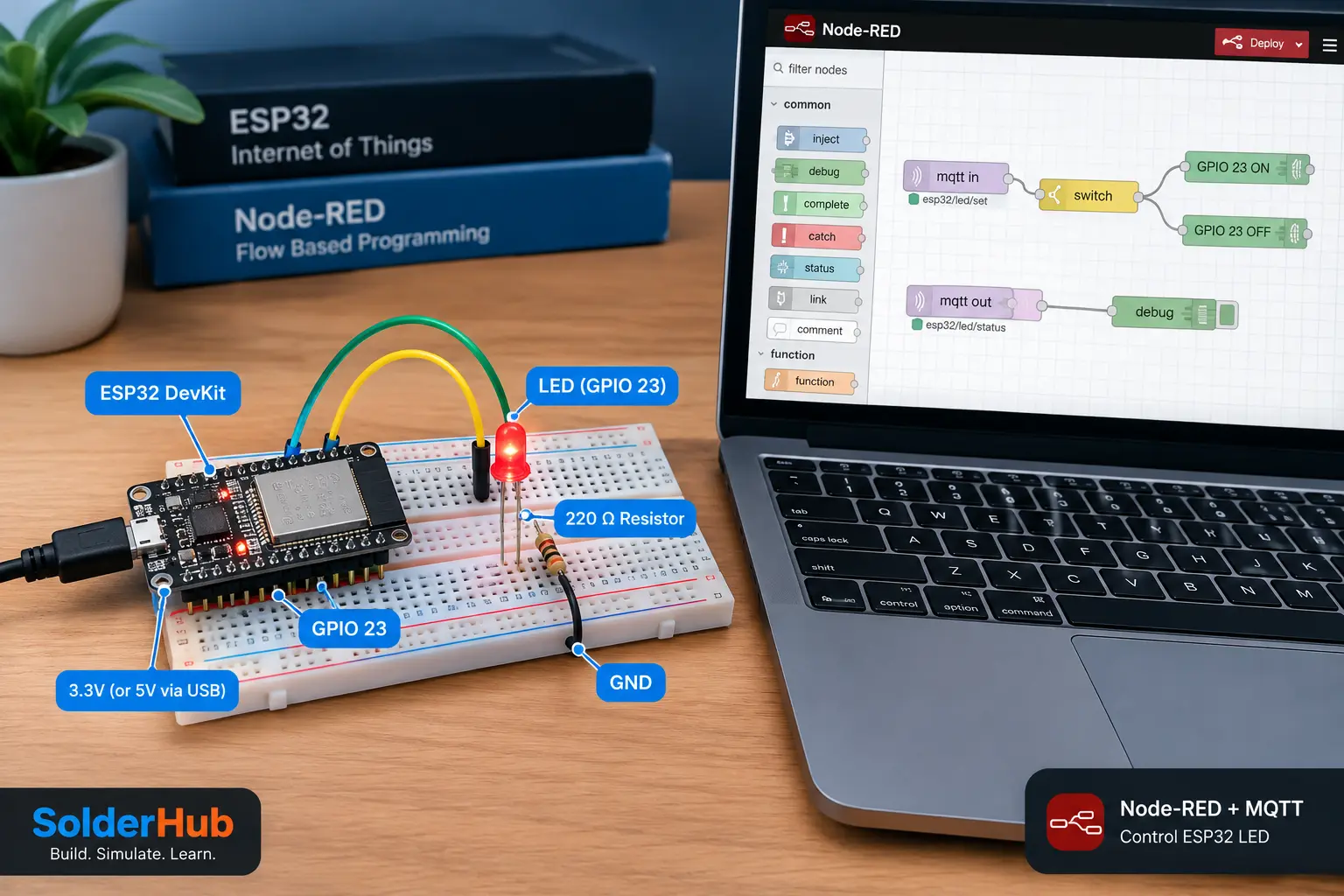
Build a real IoT control loop: click LED ON or LED OFF in Node-RED, send the command through an MQTT broker, and let an ESP32 switch an external LED. The ESP32 then publishes its reported state so Node-RED can confirm what the firmware processed.
This is a hardware project—not just a dashboard mock-up. You will wire an LED, upload Arduino IDE firmware, configure MQTT, create a Node-RED flow, test both directions, and diagnose common connection failures. You need a working Node-RED installation and an MQTT broker that both Node-RED and the ESP32 can reach.
What you will build
The control path is Node-RED → MQTT broker → ESP32 → LED. A second MQTT topic carries the ESP32's reported output state back to Node-RED. MQTT decouples the controller from the device: both clients connect to the broker rather than opening a direct connection to each other.
Parts and software
- ESP32 development board with USB data cable
- Standard LED, 220–330 Ω resistor, breadboard and jumper wires
- Computer or Raspberry Pi running Node-RED
- MQTT broker such as Mosquitto, reachable from both clients
- Arduino IDE, ESP32 board support and the PubSubClient library
We use GPIO 23 for the external LED because built-in LED pins vary across ESP32 boards. If GPIO 23 is unavailable on your exact board, select another suitable output (see the ESP32 pinout guide for pins to avoid, such as boot-strapping and input-only pins) and change LED_PIN in the sketch.
1. Wire the LED safely
Power the ESP32 from USB while programming and testing. Connect the components in series:
| ESP32 / component | Connect to |
|---|---|
| GPIO 23 | One end of a 220–330 Ω resistor |
| Resistor's other end | LED anode (usually the longer leg) |
| LED cathode (shorter leg / flat side) | ESP32 GND |
The resistor limits LED current. Never connect an LED directly to a GPIO without current limiting, and never apply 5 V to an ESP32 GPIO. ESP32 GPIOs use 3.3 V logic. Disconnect power before changing the wiring.
2. Check the MQTT broker first
Both Node-RED and the ESP32 must connect to the same broker. It may run on a Raspberry Pi, your computer, or another host on the network. If you already run a Mosquitto broker for other projects, reuse it.
Use the broker host's LAN IP address or a hostname resolvable from the ESP32. Do not put localhost or 127.0.0.1 in the ESP32 sketch when the broker is on your PC or Pi: on the ESP32, those addresses refer to the ESP32 itself. A typical local Mosquitto listener uses TCP port 1883, but use the port and authentication settings configured on your broker.
For this first project, keep the broker on a trusted network. Use authentication, restrict who can publish to control topics, and do not expose an unauthenticated MQTT listener directly to the public internet. If credentials are required, configure the same broker username and password in Node-RED and the sketch.
Quick broker test
Before touching the ESP32, confirm the broker accepts connections. The Mosquitto command-line clients ship with Mosquitto on Windows and in the mosquitto-clients package on Raspberry Pi OS and Ubuntu. Open two terminals and replace BROKER_IP with your broker's address:
# Terminal 1: listen on a test topic
mosquitto_sub -h BROKER_IP -p 1883 -t "solderhub/test" -v

# Terminal 2: publish a message
mosquitto_pub -h BROKER_IP -p 1883 -t "solderhub/test" -m "hello"
If Terminal 1 prints the message, the broker is reachable. If your broker requires a login, add -u USERNAME -P PASSWORD to both commands.
3. Upload the ESP32 firmware
In Arduino IDE, install the ESP32 board package for your board and the PubSubClient library. Select the correct board and USB port. Replace the Wi-Fi and broker settings before uploading. The example uses plain MQTT on port 1883 for a trusted local network; TLS requires a separately configured secure broker and client.
The firmware accepts only the strings ON and OFF on solderhub/esp32/led/set. It changes GPIO 23 and publishes ON or OFF to solderhub/esp32/led/status. It does not accept arbitrary GPIO commands.
#include <WiFi.h>
#include <PubSubClient.h>

const char* WIFI_SSID = "YOUR_WIFI_NAME";
const char* WIFI_PASSWORD = "YOUR_WIFI_PASSWORD";
const char* MQTT_HOST = "192.168.1.50"; // Broker host/IP reachable from ESP32
const uint16_t MQTT_PORT = 1883;
const char* MQTT_USER = "";     // Set if your broker requires authentication
const char* MQTT_PASSWORD = ""; // Set if your broker requires authentication

constexpr uint8_t LED_PIN = 23;
const char* COMMAND_TOPIC = "solderhub/esp32/led/set";
const char* STATUS_TOPIC  = "solderhub/esp32/led/status";

WiFiClient network;
PubSubClient mqtt(network);
unsigned long lastWiFiAttempt = 0;
unsigned long lastMqttAttempt = 0;
const unsigned long RETRY_INTERVAL_MS = 5000;

void publishState() {
  mqtt.publish(STATUS_TOPIC, digitalRead(LED_PIN) == HIGH ? "ON" : "OFF", true);
}

void onMessage(char* topic, byte* payload, unsigned int length) {
  if (strcmp(topic, COMMAND_TOPIC) != 0 || length > 8) return;

  char command[9] = {0};
  for (unsigned int i = 0; i < length; i++) command[i] = (char)payload[i];

  if (strcmp(command, "ON") == 0) {
    digitalWrite(LED_PIN, HIGH);
    publishState();
    Serial.println("LED set to ON");
  } else if (strcmp(command, "OFF") == 0) {
    digitalWrite(LED_PIN, LOW);
    publishState();
    Serial.println("LED set to OFF");
  } else {
    Serial.println("Ignored unknown LED command");
  }
}

void connectWiFiIfNeeded() {
  if (WiFi.status() == WL_CONNECTED) return;
  if (millis() - lastWiFiAttempt < RETRY_INTERVAL_MS) return;
  lastWiFiAttempt = millis();
  Serial.println("Connecting to Wi-Fi...");
  WiFi.mode(WIFI_STA);
  WiFi.begin(WIFI_SSID, WIFI_PASSWORD);
}

void connectMqttIfNeeded() {
  if (WiFi.status() != WL_CONNECTED || mqtt.connected()) return;
  if (millis() - lastMqttAttempt < RETRY_INTERVAL_MS) return;
  lastMqttAttempt = millis();

  uint64_t chipId = ESP.getEfuseMac();
  char clientId[32];
  snprintf(clientId, sizeof(clientId), "solderhub-%04X%08X",
           (uint16_t)(chipId >> 32), (uint32_t)chipId);

  Serial.print("Connecting to MQTT...");
  bool connected = (strlen(MQTT_USER) > 0)
    ? mqtt.connect(clientId, MQTT_USER, MQTT_PASSWORD)
    : mqtt.connect(clientId);

  if (connected) {
    Serial.println(" connected");
    mqtt.subscribe(COMMAND_TOPIC);
    publishState();
  } else {
    Serial.print(" failed, state=");
    Serial.println(mqtt.state());
  }
}

void setup() {
  Serial.begin(115200);
  pinMode(LED_PIN, OUTPUT);
  digitalWrite(LED_PIN, LOW); // Safe, known startup state
  mqtt.setServer(MQTT_HOST, MQTT_PORT);
  mqtt.setCallback(onMessage);
  connectWiFiIfNeeded();
}

void loop() {
  connectWiFiIfNeeded();
  connectMqttIfNeeded();
  if (mqtt.connected()) mqtt.loop();
  delay(10); // Short yield; reconnect attempts are timer-based
}
Set MQTT_HOST to the broker's actual LAN address. If authentication is enabled, fill in both MQTT credential strings; otherwise leave them empty. Use a unique client ID per device. The reconnect attempts are scheduled rather than trapped in a long reconnect loop, so the main loop can continue running while the network recovers.
Verify the firmware before building the flow
Open Serial Monitor at 115200 baud. You should see Wi-Fi and MQTT connection messages. If the broker connection fails, the sketch prints PubSubClient's state code; use that together with broker logs to investigate. Once connected, leave Serial Monitor open while testing commands so you can see whether the ESP32 receives and accepts them.
Test the ESP32 without Node-RED. Once the sketch is connected, you can drive it straight from a terminal. This separates firmware problems from Node-RED problems:
# Terminal 1: watch the status topic
mosquitto_sub -h BROKER_IP -p 1883 -t "solderhub/esp32/led/status" -v

# Terminal 2: send commands
mosquitto_pub -h BROKER_IP -p 1883 -t "solderhub/esp32/led/set" -m "ON"
mosquitto_pub -h BROKER_IP -p 1883 -t "solderhub/esp32/led/set" -m "OFF"
The LED should switch and Terminal 1 should print ON or OFF. If this works, the firmware and broker are fine, and any remaining problem is in the Node-RED flow.
4. Create the Node-RED command flow
Open the Node-RED editor. Add two Inject nodes and one MQTT out node, then connect both Inject nodes to the MQTT out node.
- Configure the first Inject node to send the string
ON; label it LED ON. - Configure the second Inject node to send the string
OFF; label it LED OFF. - In the MQTT out node, select the same broker and set its topic to
solderhub/esp32/led/set. - Ensure each Inject payload type is string. Do not send a Boolean or JSON object for this firmware.
- Deploy the flow.
Click the small button on the LED ON Inject node to publish the command. Click LED OFF to turn the output off. These Inject controls provide a simple first test without requiring a dashboard package.
5. Add device status feedback
To see the ESP32's response, add an MQTT in node and a Debug node, then wire MQTT in to Debug. Select the same broker and set the subscription topic to solderhub/esp32/led/status. Deploy the flow and open the Debug sidebar.
Click LED ON: the physical LED should light, Serial Monitor should show the command was accepted, and Node-RED Debug should receive ON. Click LED OFF and confirm the corresponding OFF response.
The firmware publishes status as a retained MQTT message, so a new subscriber can immediately receive the last reported state. Retained state can be stale if a device disconnects unexpectedly; treat this as the firmware's last reported output state, not proof that the LED or wiring is physically working.
Troubleshooting checklist
- The LED never changes: check the LED polarity, resistor, common GND and GPIO 23. Make sure
LED_PINmatches the physical wire. - The ESP32 cannot connect to Wi-Fi: verify the SSID/password and signal. ESP32 boards generally require a 2.4 GHz Wi-Fi network, not a 5 GHz-only network.
- MQTT does not connect: confirm the broker address is reachable from the ESP32, the listener is enabled, the port and credentials are correct, and the broker firewall permits the connection. Do not use
localhostin the ESP32 sketch for a broker running elsewhere. - Node-RED's MQTT node reports disconnected: check the broker configuration and its status indicator, then inspect broker logs. Confirm both clients use the same broker, not merely the same topic name.
- Inject clicks work but the ESP32 ignores them: verify the exact command topic, string payload type, case (
ON/OFF), and the ESP32 subscription. Check Serial Monitor for received-command messages. - No status appears in Debug: confirm the MQTT In node subscribes to
solderhub/esp32/led/status, deploy the flow, and enable the Debug sidebar. - The device reconnects repeatedly: check signal strength, broker availability, authentication, and client ID uniqueness. Inspect
mqtt.state()output and broker logs.
For diagnosis, print the received topic and payload temporarily if needed, but never log or publish passwords.
Security and safe operation
This example uses plain MQTT on port 1883 for a trusted local network; that traffic is not encrypted unless you configure TLS. Enable broker authentication and topic-level permissions so only authorized clients can publish to solderhub/esp32/led/set. Do not forward an unauthenticated MQTT port from your router to the internet. For remote access, use a VPN or a properly secured TLS-enabled broker.
Keep Wi-Fi credentials and broker passwords out of public screenshots, articles and source repositories. If you later adapt this pattern to a relay, motor or pump, add explicit safe startup behavior, authorization and hardware protections; do not treat this LED example as a mains-control design.
Extend the project
After the LED control works, replace the two Inject nodes with a FlowFuse Dashboard 2.0 switch, publish sensor readings from the ESP32, or add separate topics for more outputs. Keep command topics separate from reported-state topics and define what the device should do after a reboot or broker outage.
If Mosquitto runs on a Raspberry Pi 5, the architecture stays the same as long as the ESP32, Node-RED runtime and broker can reach one another over the network.
Frequently asked questions
Can I use the ESP32's built-in LED?
Possibly. Built-in LED pins and polarity vary by board. An external LED on GPIO 23 makes the circuit explicit; if using the onboard LED, check the exact board pinout and change LED_PIN accordingly.
Does Node-RED connect directly to the ESP32?
No. In this design, Node-RED and the ESP32 are separate MQTT clients. The broker receives the command and forwards it to clients subscribed to the matching topic.
Can I control the LED from outside my home network?
Yes, with a properly secured remote setup. Do not expose an unauthenticated MQTT listener to the internet. Prefer a VPN or a broker configured with TLS, authentication and topic permissions.
Why use MQTT instead of a direct HTTP request?
MQTT's publish/subscribe model makes it easy to add other devices or monitoring flows without changing the controller-to-device architecture.
Conclusion
You have built a reusable real-hardware IoT pattern: Node-RED publishes a command, MQTT routes it to the ESP32, the ESP32 changes a GPIO output, and a status topic reports the firmware's response. The same pattern can support sensor dashboards and multi-device automation when you keep topics, credentials and failure behavior well designed.