
Introduction
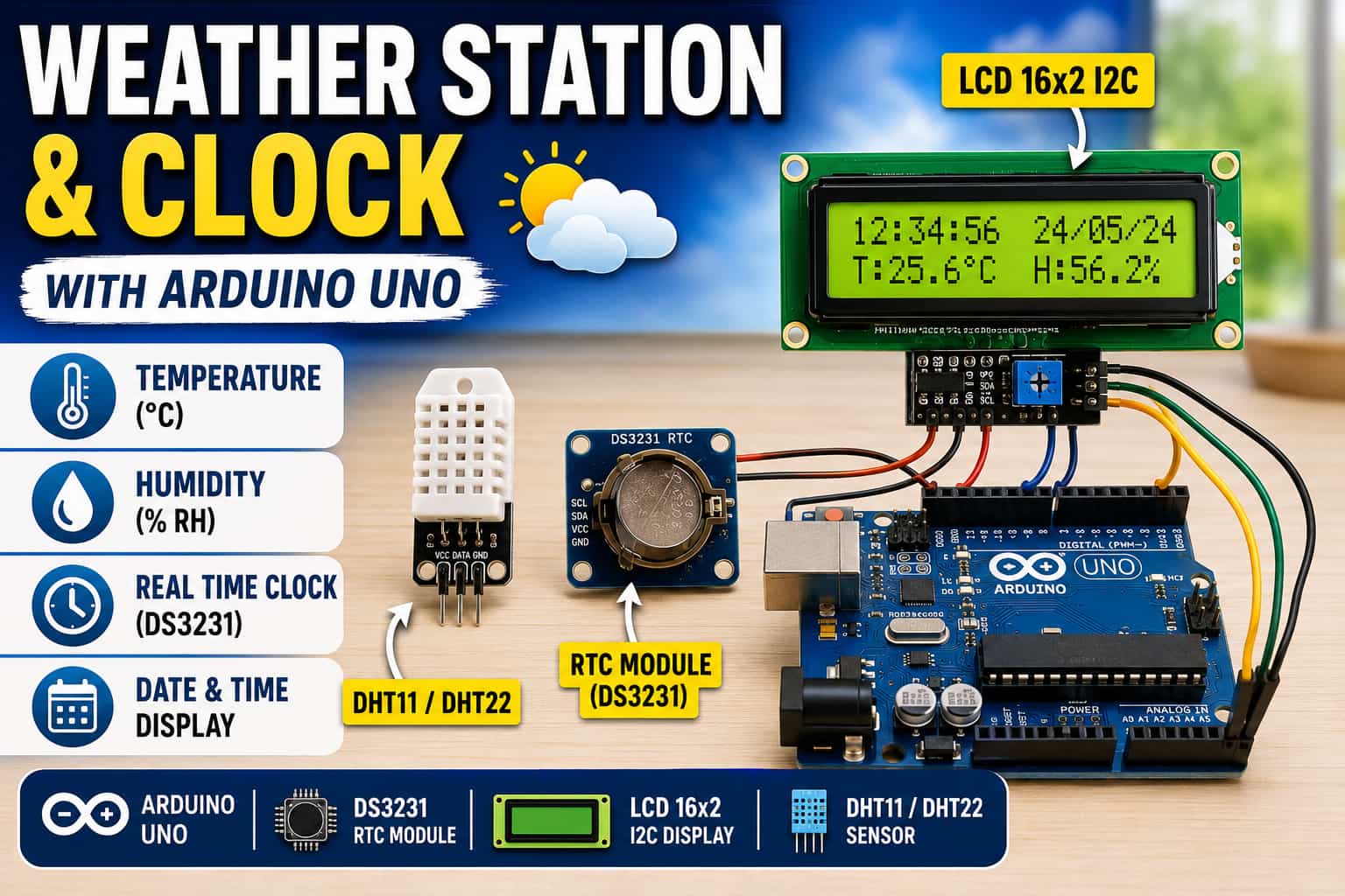
In this tutorial you will build a complete desktop weather station and clock using an Arduino Uno. The final device will show:
-
1. Current time(hours:minutes:seconds)
-
2. Date (day/month)
-
3. Temperature (°C)
-
4. Relative humidity (%)
You have the option to use either a DHT11 or a DHT22 sensor. The DHT22 is more accurate compared to DHT11 (we will cover the comparison later ). However DHT11 is more affordable and cost effective.
All information is displayed on a 16x2 LCD with an I2C backpack, saving most of your Arduino pins.
What you will learn :-
-
Reading digital temperature/humidity with the DHT family.
-
Keeping accurate time with a DS3231 Real Time Clock (I2C).
-
Connecting multiple I2C devices (LCD + RTC) using only two pins.
-
Writing clean, non‑blocking code with millis().
-
Switching between DHT11 and DHT22 with a single line change.
Components
7 itemsNeed these parts? Get this build sheet by email
Parts list with buy links, plus new builds as they're published. By subscribing you agree to our Privacy Policy. Unsubscribe anytime.
Choosing Between DHT11 and DHT22
| Feature | DHT11 | DHT22 (AM2302) |
|---|---|---|
| Temperature range | 0 – 50°C | -40 – 80°C |
| Temperature accuracy | ±2°C | ±0.5°C |
| Humidity range | 20 – 90% RH | 0 – 100% RH |
| Humidity accuracy | ±5% RH | ±2‑5% RH |
| Sampling rate | 1 Hz (1 read/sec) | 0.5 Hz (1 read/2 sec) |
| Cost | Low (~$3) | Higher (~$10) |
| Recommendation: |
- Use DHT22 if you want better accuracy, wider range.
- Use DHT11 if you want a low budget hobby project and only need basic monitoring in a room environment.
Both sensors use the same wiring and the same library – only the DHTTYPE definition changes.
Understanding the Components
DHT11 / DHT22 Sensor
Both sensors contain a capacitive humidity sensor, a thermistor, and a small microcontroller that outputs a calibrated digital signal. You do not need to build any voltage divider – just connect VCC, GND, and the data pin.
Pull‑up resistor requirement:
The data line needs a 10kΩ pull‑up resistor between the data pin and VCC. Most module‑style sensors (with 3 pins) include this resistor. If you have a bare 4‑pin DHT sensor, you must add a 10kΩ resistor yourself.
DS3231 RTC Module
The DS3231 is a highly accurate Real Time Clock with a built‑in temperature‑compensated crystal oscillator (TCXO). It keeps time even when the Arduino is unplugged, thanks to a backup battery (CR2032). It communicates over I2C.
16x2 I2C LCD
The I2C backpack reduces the typical 6‑pin parallel interface to just 2 pins (SDA, SCL). This leaves most of your Arduino pins free for other sensors or actuators.
Wiring Diagram (Step‑by‑Step)
All three modules share the same 5V and GND rails. The LCD and RTC share the I2C bus (SDA, SCL). The DHT sensor connects to a separate digital pin (pin 2).
Pin Connections Table
| Arduino Uno | DS3231 RTC | I2C LCD | DHT11 / DHT22 (3‑pin module) | Notes |
|---|---|---|---|---|
| 5V | VCC | VCC | VCC | Red wire → breadboard + rail |
| GND | GND | GND | GND | Black wire → breadboard – rail |
| A4 (SDA) | SDA | SDA | – | Yellow wire to both SDA pins |
| A5 (SCL) | SCL | SCL | – | Green wire to both SCL pins |
| Pin 2 | – | – | DATA (OUT) | Blue wire from sensor |
If using a bare 4‑pin DHT11/22:
- Pin 1 → 5V
- Pin 2 → DATA → 10kΩ resistor → 5V (pull‑up) and also to Arduino pin 2
- Pin 3 → not connected
- Pin 4 → GND
Visual Instructions
- Place the Arduino Uno at one end of the breadboard.
- Plug the I2C LCD onto the breadboard.
- Place the DS3231 module and the DHT sensor on the remaining free area.
- Connect the red rail of the breadboard to Arduino 5V.
- Connect the blue rail to Arduino GND.
- Connect VCC of LCD, RTC, and DHT to the red rail.
- Connect GND of LCD, RTC, and DHT to the blue rail.
- Connect A4 (Arduino) to SDA on LCD and SDA on RTC.
- Connect A5 (Arduino) to SCL on LCD and SCL on RTC.
- Connect Pin 2 (Arduino) to the DATA pin of the DHT sensor.
(Insert a Fritzing diagram or clear photo here)
Installing the Required Libraries
Open the Arduino IDE, go to Sketch → Include Library → Manage Libraries… and install:
| Library | Author | Search Term |
|---|---|---|
| DHT sensor library | Adafruit | DHT sensor library |
| RTClib | Adafruit | RTClib |
| LiquidCrystal I2C | Frank de Brabander (or Marco Schwartz) | LiquidCrystal I2C |
The DHT library will also install Adafruit Unified Sensor – accept it.
Complete Arduino Code (Compatible with DHT11 and DHT22)
Copy and paste the following code. Only one line determines which sensor you use.
Upload and Test Connect your Arduino Uno to your computer via USB.
Select Board: Arduino Uno and the correct Port.
Click Upload.
Expected output on LCD (after setting the RTC time): Time: 14:35:22 45% Date: 04/06 23.5C The values will update every second.
Setting the RTC Time (Very Important) The RTC module keeps time even when powered off, but it must be set once after you first install the battery.
In the code, uncomment the line:
rtc.adjust(DateTime(F(__DATE__), F(__TIME__)));
Upload the code. This sets the RTC to your computer's compile time.
Re‑comment that line (add // at the front) and upload again. Otherwise, the time will reset every time you power on the Arduino.
Alternatively, you can set a specific date/time manually:
rtc.adjust(DateTime(2026, 6, 4, 15, 30, 0));
Troubleshooting Guide
Problem Most Likely Cause How to Fix
- LCD backlight on but no text Wrong I2C address Change 0x27 to 0x3F or run an I2C scanner.
- LCD shows solid blocks Contrast potentiometer Turn the blue screw on the back of the LCD.
- “RTC Error!” message RTC not connected or no battery Check SDA→A4, SCL→A5, 5V, GND. Insert CR2032 battery.
- Time resets after power off RTC never set Uncomment rtc.adjust(...), upload, then re‑comment and upload again.
- “Sensor Error!” on LCD DHT wiring or missing pull‑up Check VCC, GND, DATA pin. Add a 10kΩ pull‑up resistor if missing.
- Temperature reads 0.0°C Using DHT22 but code set to DHT11 (or vice versa) Change DHTTYPE to match your sensor.
Next Steps & Project Extensions Your weather station is now complete. Here are some natural upgrades:
Display Fahrenheit Add
float f = temperatureC * 9.0/5.0 + 32.0;
and show both units.
Data logging
-
Add a microSD card module to log temperature, humidity, and timestamps to a CSV file.
-
Switch to ESP32 / NodeMCU Use the exact same DHT and RTC code, but add Wi‑Fi to send data to Blynk, ThingSpeak, or a local web server.
-
Build a standalone gadget Replace the Uno with an Arduino Nano, add a battery pack, and 3D‑print a case.
-
Add an alarm Use the DS3231’s built‑in alarms to trigger a buzzer or LED when temperature exceeds a threshold.
Conclusion
We have just built a fully functional real‑time weather station and clock using an Arduino Uno, a DHT11 or DHT22 sensor, a DS3231 RTC, and an I2C LCD. You learned:
How to read temperature and humidity from the DHT family.
How to keep accurate time with a battery‑backed RTC.
How to connect multiple I2C devices (LCD + RTC) with only two wires.
How to switch between DHT11 and DHT22 with a single line change.
How to simulate the entire project on Wokwi (using DHT22).
This project gives you a solid platform for more advanced builds like remote environmental monitors, data loggers, and home automation controllers.
Now it’s your turn: Build it, experiment with it, and share your results with the SolderHub community. If you run into any issues, refer to the troubleshooting guide or ask a question in the comments.
Happy making!
Related tutorials:
How to Add an SD Card Logger to Your Weather Station
ESP32 Web Server: Monitor DHT22 from Anywhere
Using the DS3231 Alarm to Wake Up Your Arduino
Weather station and clock: wiring, timekeeping, and validation
Plan the shared connections
This build combines a temperature/humidity sensor, a DS3231 real-time clock (RTC), and a 16×2 LCD. Check the exact sensor and display interfaces used by your sketch before wiring. An I2C LCD backpack and the DS3231 can generally share the I2C bus when their addresses do not conflict; an I2C sensor may share it as well. A non-I2C LCD uses a different set of digital pins. On an Uno, SDA/SCL are the board’s I2C pins; verify the pinout for other boards rather than assuming the same mapping.
Sensor choice matters
DHT11 and DHT22 are not identical: their measurement range, resolution, and timing differ. Use the model named in the sketch and allow the required interval between readings. Avoid placing the sensor directly above the microcontroller regulator or in direct sunlight, since local heating can skew the result. If the displayed temperature looks wrong, compare it with a trusted thermometer after both have stabilized in the same location.
RTC setup and battery behavior
Set the RTC time intentionally during initial setup, then avoid resetting it on every boot. If the sketch resets the clock each time it starts, the displayed time may jump back to the compile time. Check the RTC module’s backup battery and confirm the clock continues while main power is disconnected. A battery is for timekeeping backup, not for powering the LCD and controller.
Bring-up checklist
- Test the controller and LCD first, confirming readable text and correct contrast.
- Detect the RTC and sensor independently before integrating the full display loop.
- Confirm the RTC time is set once and remains correct after a restart.
- Check that the sensor model in the code matches the hardware.
- Verify that slow sensor reads do not make the clock display appear frozen.
- Keep wiring diagrams and pin constants aligned; use the actual sketch as the source of truth if a pin differs from a generic example.
Troubleshooting
- LCD backlight is on but no text appears: check contrast, I2C address or parallel pin mapping, and initialization.
- RTC is not detected: inspect SDA/SCL, power, ground, address, and library initialization.
- Time resets after reboot: check whether the code resets the clock during every startup and inspect the RTC backup battery.
- Temperature or humidity jumps: verify the sensor model, sampling interval, placement, and power stability.
- Display updates slowly: separate sensor sampling from display refresh where practical, and avoid long blocking delays in the main loop.
Make the readings reproducible
When sharing results, list the exact sensor and RTC modules, library names, board, wiring, and how the time was initialized. State that a hobby sensor is suitable for learning and general observation, not a substitute for calibrated instruments when precise environmental measurements are required.

