

Motion
Interfacing A3144 Motion with Arduino Uno
What is the A3144?
The A3144 is a digital Hall-effect switch: it detects a magnetic field and changes its OUT pin between a low state and a released state. It is useful for contactless RPM counters, wheel-speed sensing, door and lid detection, position switches, and simple motor feedback. Unlike a reed switch, it has no moving contacts to wear out. Unlike an analog Hall sensor, it is intended to behave like a switch rather than provide a continuously varying magnetic-field measurement.
This guide covers the bare three-lead A3144, its open-collector output, safe wiring, and practical integrations with Arduino Uno and ESP32. Different manufacturers and inexpensive modules can vary, so use the markings and datasheet for the exact part you own.
Warning
**Electrical limit:** the commonly documented bare A3144 operates from approximately 4.5–24 V. Do not assume a bare sensor is a 3.3 V device. On an ESP32, power the sensor from 5 V, connect grounds, and pull OUT up to 3.3 V with an external resistor. This is safe only when OUT is truly open-collector and the module does not also pull the line up to 5 V.
A3144 specifications
- Sensor type
- Digital Hall-effect switch
- Supply voltage (bare device)
- About 4.5–24 V DC; check exact datasheet
- Output
- Open collector, active LOW
- Output HIGH
- Requires an external or internal pull-up
- Magnetic response
- Switching depends on field strength and pole orientation
- Interface
- One digital signal; no I²C/SPI protocol
- Common uses
- RPM, wheel speed, position, lid/door state
- Board compatibility
- 5 V Arduino; 3.3 V GPIO boards with correct pull-up
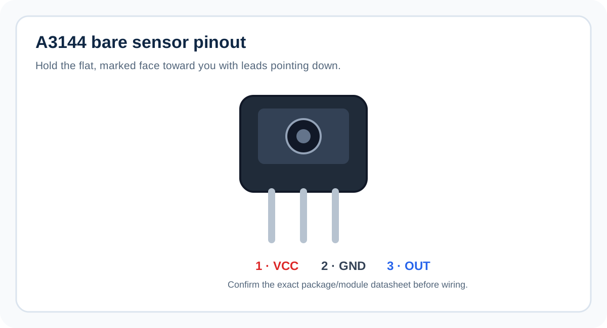
Bare A3144 pinout
| Pin | Name | Function |
|---|---|---|
| 1 | VCC | Positive supply. Use the voltage specified for the exact device; commonly 5 V in these projects. |
| 2 | GND | Ground reference. Connect to the microcontroller ground. |
| 3 | OUT | Open-collector digital output. Pull it up to the logic voltage expected by the board. |
Swipe sideways to see every column →
The pin numbering above follows the common A3144E three-lead package convention when the marked/flat face is toward you and the leads point downward. Package variants, clones, and breakout boards may arrange pins differently. Check the exact part’s datasheet or PCB silkscreen instead of relying on package appearance alone.
How the A3144 detects a magnet
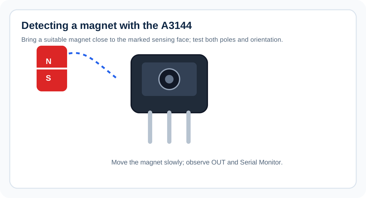
The Hall element responds to magnetic flux passing through the sensing region. Internal circuitry compares the field with a switching threshold and controls an output transistor. When the required magnetic pole and field strength are present, the transistor conducts and pulls OUT toward GND. When the field is absent or below the release threshold, the transistor stops conducting and OUT is released.
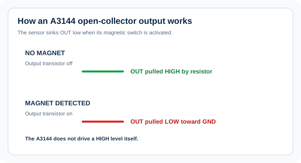
Because OUT is open collector, the sensor can pull the line LOW but does not actively drive it HIGH. A pull-up resistor supplies the HIGH level. On an Arduino Uno, INPUT_PULLUP enables the board’s internal pull-up and is normally adequate for a short, simple connection. On an ESP32, use a pull-up to 3.3 V; a 10 kΩ resistor is a good starting point. Never pull an ESP32 GPIO up to 5 V.
The switching threshold includes hysteresis, so the turn-on and release fields are not identical. This helps prevent chatter near the threshold. It does not mean every magnet will trigger the sensor at the same distance: magnet size, pole, orientation, air gap, and the exact sensor revision all matter.
Output states and logic
| Physical state | A3144 output transistor | OUT voltage with a pull-up | digitalRead() |
|---|---|---|---|
| No triggering field | Off / released | HIGH | HIGH |
| Triggering field present | On / sinking current | LOW, near GND | LOW |
For this reason, example code treats LOW as “magnet detected.” If your serial output appears inverted, first verify the output wiring, pull-up, and magnetic pole/orientation. Some modules add components that alter the signal behavior, so confirm what your particular module exposes at OUT.
What you can build
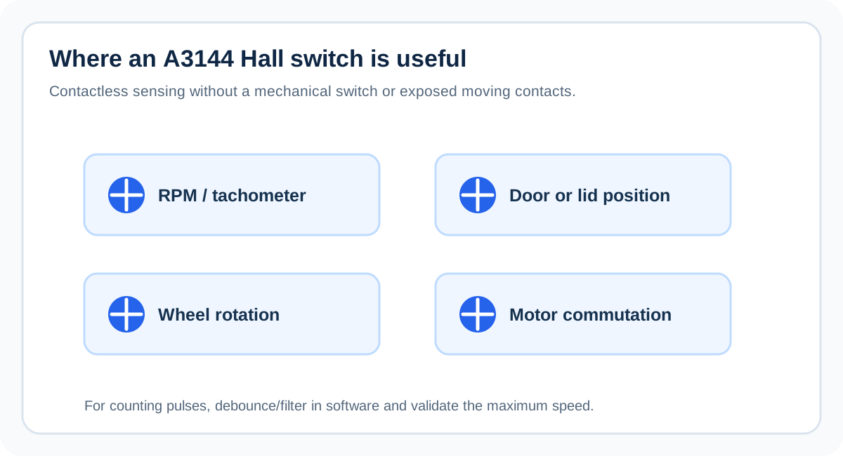
- RPM counter: place a magnet on a rotating shaft or wheel and count each active pulse. For one magnet per revolution, RPM equals pulses per minute. For multiple magnets, divide by the number of pulses per revolution.
- Wheel-speed sensor: detect a magnet attached to a wheel and convert pulse frequency to speed using wheel circumference and magnet count.
- Door or lid detector: position a magnet so the sensor changes state when the door closes or opens. Design the mounting so the magnet cannot strike the sensor.
- Position or end-stop indicator: detect whether a moving mechanism has reached a particular location. A Hall switch is not a substitute for a safety-rated limit switch in machinery where failure could cause injury.
- Motor feedback: detect a rotating magnetic target. Motor commutation requires appropriate sensor placement, pole count, timing, and driver design; a single sensor alone may not provide all the signals a controller needs.
Wiring and design best practices
- Check the exact sensor. Bare A3144 parts, compatible replacements, and breakout modules are not interchangeable by appearance alone. Verify supply range and pin order.
- Share ground. The sensor and microcontroller need a common GND reference, even when the output pull-up is connected to a separate logic rail.
- Use the right pull-up voltage. Use the Uno’s internal pull-up for a simple 5 V Uno setup. For ESP32, pull OUT to 3.3 V with a resistor. If a module has a built-in pull-up to 5 V, do not connect it directly to an ESP32 GPIO; remove/disable that pull-up if appropriate or use a suitable level shifter.
- Keep leads short. Long wires pick up noise. Route the signal away from motor and relay wiring; add filtering or software debounce if needed.
- Count edges, not repeated states. For RPM measurement, count transitions and measure the interval between them. Printing the current state every few milliseconds is not the same as counting revolutions.
- Test the target magnet. Slowly move the magnet across the sensing face, try the pole specified by the datasheet, and check both activation and release.
- Treat the sensor as a switch. The A3144 does not report field strength or distance. If you need analog field measurements, choose an analog Hall sensor or a suitable digital magnetic sensor with the required interface.
Troubleshooting
| Symptom | Likely cause | What to check |
|---|---|---|
| OUT always reads HIGH | No triggering field, wrong pole/orientation, sensor not powered, or open output with pull-up | Verify VCC/GND, test the specified pole close to the sensing face, and check pin order. |
| OUT always reads LOW | OUT shorted to GND, incorrect pinout, damaged sensor, or field permanently present | Disconnect OUT from the board and test safely; inspect for solder bridges and wiring errors. |
| ESP32 resets or GPIO behaves unpredictably | Incorrect wiring, 5 V pull-up on GPIO, or noisy supply | Ensure OUT is pulled up only to 3.3 V; verify common ground and supply stability. |
| Sensor works on bench but not with a motor | Electrical noise, long wires, weak magnet, or unsuitable placement | Shorten/route signal wiring, improve mounting, and add measured filtering if necessary. |
| RPM count jumps at low speed | Repeated polling counts a held state or signal noise creates extra edges | Count only transitions; add a sensible debounce interval and validate with known revolutions. |
| It triggers at a different distance than expected | Different magnet strength, pole, angle, air gap, or device threshold | Test the real magnet and consult the exact manufacturer datasheet. |
Frequently asked questions
Is the A3144 analog or digital? It is a digital Hall-effect switch. Its output indicates a threshold crossing; it does not measure magnetic field strength as an analog voltage.
Does OUT need a resistor? OUT needs a pull-up to become HIGH. The Uno’s internal pull-up is suitable for a short basic circuit. The ESP32 example uses an external 10 kΩ pull-up to 3.3 V. A module may already contain a pull-up, so inspect it before adding another.
Can I power a bare A3144 from 3.3 V? Do not assume so. The commonly documented A3144 supply range starts around 4.5 V. Use the datasheet for your exact part. A breakout advertised as 3.3 V compatible may include a different sensor or additional circuitry.
Can I connect a 5 V A3144 directly to an ESP32? Not if OUT can rise to 5 V. Use an open-collector arrangement with a pull-up to 3.3 V and ensure there is no hidden 5 V pull-up on the module, or use a suitable level shifter.
Will every magnet trigger it? No. Magnetic pole, orientation, strength, gap, and the device’s operate/release thresholds determine whether it switches.
Can it measure RPM? Yes. Count one or more output pulses per revolution and calculate RPM from the measured pulse rate. Add filtering for noise and use an interrupt or edge-timing approach when speed increases.
Is the simulator proof that my physical circuit works? No. The saved circuit helps you inspect connections and code, but magnetic sensing depends on real field strength and orientation. Test the actual component on the bench before relying on it in a finished product.
Continue learning: Arduino Uno pinout · ESP32 pinout · Hall-effect sensor projects · Explore SolderHub Simulator
Setting Up A3144 with Arduino Uno
This integration reads a bare A3144 digital Hall-effect switch with an Arduino Uno. The sensor is powered from the Uno’s 5 V rail, and its open-collector OUT pin connects to D2. The sketch enables INPUT_PULLUP, so the inactive output is HIGH and a detected magnetic field pulls D2 LOW.
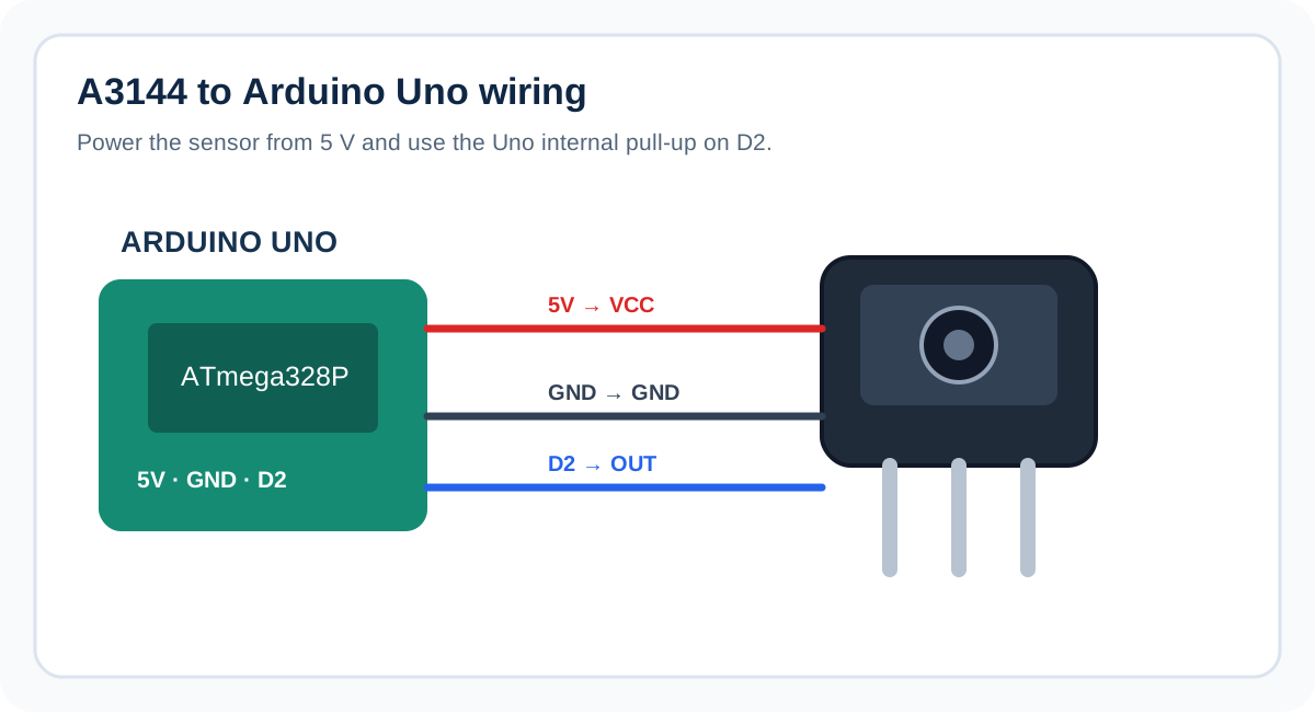
Wiring: A3144 to Arduino Uno
| A3144 pin | Arduino Uno pin | Reason |
|---|---|---|
| VCC | 5V | Power for the bare A3144; verify the exact device rating. |
| GND | GND | Common reference. |
| OUT | D2 | Digital input; internal pull-up enabled in code. |
Swipe sideways to see every column →
Try this circuit — SolderHub Simulator
The circuit is preloaded for exploration. Confirm simulator behavior against the real wiring and sensor datasheet before connecting hardware.
- 1With USB disconnected, identify VCC, GND, and OUT from the sensor datasheet or module labels.
- 2Connect VCC to Uno 5V, GND to Uno GND, and OUT to D2.
- 3Connect the Uno to your computer and open Arduino IDE.
- 4Select Arduino Uno and the correct port. Paste the sketch below and upload it.
- 5Open Serial Monitor at 9600 baud. Move the correct pole of a magnet close to the sensing face and then move it away.
Expected Serial Monitor output
With no triggering magnetic field, the monitor prints No magnet detected. When the sensor switches, it prints Magnet detected. The loop repeats every 200 ms, so the same state may appear multiple times while the magnet remains in place. This is intentional for a beginner test; an RPM counter should count transitions rather than count every printed line.
Troubleshooting
- Always HIGH: check supply and pin order, and test the correct magnetic pole closer to the sensing face.
- Always LOW: verify OUT is not shorted to GND and the sensor is not held in its active field.
- No serial text: confirm the selected port and 9600 baud rate.
- Unstable readings: shorten leads, share a solid ground, and keep the signal wire away from motors or relays.
INPUT_PULLUP is appropriate for a short Uno test. If you use long wiring or a noisy installation, test signal integrity and consider an external pull-up selected for the cable and sensor rather than assuming the internal resistor is ideal.
Turning the switch into an RPM counter
For RPM, use a magnet fixed securely to the rotating part and count one chosen edge per pass. With one magnet per revolution, RPM = pulsesPerMinute; with N magnets, RPM = pulsesPerMinute / N. For better accuracy, use an interrupt on D2 and measure elapsed time between edges with micros(), adding a minimum interval that rejects impossible pulses. Secure the magnet mechanically and keep it away from components where it could detach.
FAQ
Do I need an external resistor on Uno? For a basic short-wire circuit, INPUT_PULLUP enables an internal pull-up. A module may already include one. For noisy or long-wire installations, validate the circuit and use an appropriate external pull-up if needed.
Can I use another digital pin? Yes; change HALL_PIN and wire OUT to that pin. D2 is convenient and supports external interrupts on the Uno.
Is the embedded simulator a physical sensor test? No. It opens the saved SolderHub circuit for exploring its wiring and sketch. A physical magnet and sensor are still required to verify real magnetic switching.
Related Components

DHT11
The classic beginner temperature and humidity sensor — cheap, factory-calibrated and supported on every board.

DS18B20
The 1-Wire digital thermometer that survives water, soil and long cables, with a unique address so many probes can share one pin.
HC-SR04
The most reliable ultrasonic distance sensor — measure 2cm to 4m with just two GPIO pins.
Related Guides & Projects
Arduino Uno R4 Minima Pinout: Every GPIO, ADC, DAC, and Op-Amp Pin Explained
A complete Arduino Uno R4 Minima pinout reference — digital I/O, ADC, DAC, op-amp, CAN, dual UART, and exactly what it leaves out compared to the WiFi variant.
Mastering PWM on Arduino: Dimming LEDs and Controlling Motors
Understand what PWM actually is on Arduino, dim an LED smoothly, and safely control a DC motor's speed with a driver chip -- plus the mistakes (like wiring a motor straight to a pin) that damage boards.
4-Digit 7-Segment Counter with TM1637 & Arduino
Drive a TM1637-based 4-digit 7-segment display with Arduino Uno to show a real-time up/down counter, elapsed timer, and scrolling text. Covers library setup, brightness control, and custom segment mapping.
Arduino Uno R4 Minima vs WiFi: Which One Should You Choose?
Same processor, same memory, different price. Here's what the WiFi variant's extra hardware actually gets you, and when the Minima is the smarter buy.