
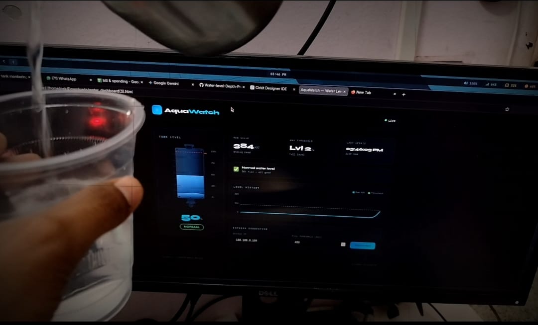
💧 AquaWatch — ESP8266 Water Level Monitor
A self-hosted water tank monitoring system using an ESP8266 and HS-S37P water depth sensor. Your device serving a live dashboard on your local network.
📸 Features
- 4-level water detection using the HS-S37P analog sensor
- Animated tank visualization on a live web dashboard
- Buzzer alert triggers when water reaches Level 4 (top line)
- Full-screen popup alert on the dashboard when tank is full
- Live history chart of sensor readings
- Self-hosted — ESP8266 runs its own web server, no internet needed
- Demo mode — dashboard previews with simulated data when not connected
🧰 Hardware Required
| Component | Details |
|---|---|
| ESP8266 | NodeMCU or Wemos D1 Mini |
| HS-S37P | Water depth / level sensor |
| Buzzer | Active buzzer (3.3V or 5V) |
| Jumper wires | Male-to-female |
| Power supply | USB or 5V adapter |
🔌 Wiring
HS-S37P Sensor          ESP8266
──────────────          ───────
    S  ──────────────►  A0   (analog signal)
    +  ──────────────►  3.3V (VCC)
    G  ──────────────►  GND

Buzzer                  ESP8266
──────────────          ───────
   +   ──────────────►  D2 / GPIO4
   -   ──────────────►  GND
Note: The HS-S37P has 4 exposed sensing traces. As water rises and bridges more traces, the analog voltage on A0 increases in steps.
🚀 Setup Guide
1. Flash the Firmware
- Open
aquawatch_esp8266.inoin Arduino IDE - Install required libraries if not already present:
ESP8266WiFi(comes with ESP8266 board package)ESP8266WebServer(comes with ESP8266 board package)
- Set your WiFi credentials:
const char* ssid = "Your_WiFi_Name"; const char* password = "Your_Password"; - Select your board: Tools → Board → NodeMCU 1.0 (or your variant)
- Upload the sketch
2. Calibrate the Sensor
The HS-S37P gives a rising ADC value as more of the sensor is submerged. You need to find the ADC value at each of the 4 sensor lines:
- Open Serial Monitor at
115200baud - Dip the sensor to each line, one at a time, and note the ADC value printed
- Update the thresholds in the firmware:
#define LEVEL1_MIN   50    // ADC > this → Level 1 (bottom line)
#define LEVEL2_MIN  200    // ADC > this → Level 2
#define LEVEL3_MIN  350    // ADC > this → Level 3
#define LEVEL4_MIN  515    // ADC > this → Level 4 ← buzzer triggers here
These are typical values for a 3.3V supply. Your sensor may vary — always calibrate.
3. Find the Device IP
After flashing, open Serial Monitor. You will see:
AquaWatch — HS-S37P 4-Level Build
───────────────────────────────────
Connected!
IP: 192.168.1.105
Server ready.
Note the IP address.
4. Open the Dashboard
- Open
water_dashboard.htmlin any browser on the same WiFi network - Enter the device IP in the Device IP field (e.g.
192.168.1.105) - Click Connect — the dashboard starts polling every second
📊 How the Sensor Works
The HS-S37P is not a true ultrasonic depth sensor. It works by detecting electrical conductivity between exposed copper traces on the sensor PCB. As water rises:
| Water touches... | ADC range (approx) | Level shown |
|---|---|---|
| Nothing (dry) | 0 – 50 | 0% |
| Line 1 (bottom) | 50 – 200 | 25% |
| Line 2 | 200 – 350 | 50% |
| Line 3 | 350 – 450 | 75% |
| Line 4 (top) | 450+ | 100% 🚨 |
When Level 4 is reached:
- Buzzer beeps (250ms on / 300ms off pattern)
- Dashboard tank turns red
- Full-screen alert popup appears with an ACKNOWLEDGE button
🌐 API Endpoint
The ESP8266 serves a JSON endpoint at http://<device-ip>/data:
{
  "level": 600,
  "waterLevel": 4,
  "threshold": 515,
  "percent": 100,
  "isFull": true,
  "status": "FULL"
}
| Field | Description |
|---|---|
level | Raw ADC value (0–1023) |
waterLevel | Detected level 0–4 |
threshold | ADC value for Level 4 trigger |
percent | Percentage (waterLevel × 25) |
isFull | true when Level 4 is reached |
status | DRY / NORMAL / HIGH / FULL |
⚙️ Configuration Reference
Firmware (aquawatch_esp8266.ino)
| Constant | Default | Description |
|---|---|---|
LEVEL1_MIN | 50 | ADC threshold for Level 1 |
LEVEL2_MIN | 200 | ADC threshold for Level 2 |
LEVEL3_MIN | 350 | ADC threshold for Level 3 |
LEVEL4_MIN | 450 | ADC threshold for Level 4 (buzzer) |
BEEP_ON_MS | 250 | Buzzer ON duration per beep (ms) |
BEEP_OFF_MS | 300 | Buzzer OFF duration per beep (ms) |
Dashboard (water_dashboard.html)
Settings are entered directly in the UI:
| Field | Description |
|---|---|
| Device IP | IP address of your ESP8266 |
| Full Threshold (ADC) | Reference ADC value shown in stats |
🛠️ Troubleshooting
Buzzer beeps immediately on power-up → That is intentional — a single short beep on startup confirms the buzzer works.
ADC reads random values / sensor noisy → Add a 10kΩ pull-down resistor between A0 and GND. Also ensure stable 3.3V supply.
Dashboard shows "Disconnected"
→ Make sure your browser and ESP8266 are on the same WiFi network. Some browsers block HTTP fetch from a local file — try serving the HTML via a local server or use the ESP8266's / page directly.
Sensor degrading over time → The HS-S37P copper traces corrode with prolonged water contact. For longer life, only insert the sensor into water when needed, or coat the non-sensing back side with silicone sealant.
Compilation error: 'D2' not declared
→ The firmware uses raw GPIO numbers (#define BUZZER_PIN 4) instead of Arduino-style macros to avoid this. If you change pins, use the GPIO number, not the D-label (e.g. D2 = GPIO4, D1 = GPIO5).
📌 Pin Reference (NodeMCU)
| NodeMCU Label | GPIO | Used for |
|---|---|---|
| A0 | ADC0 | Sensor signal (S) |
| D2 | GPIO4 | Buzzer (+) |
📜 License
MIT — free to use, modify, and distribute.
Built with ESP8266 Arduino Core · No cloud dependencies
Water level monitor: calibration, installation, and fault checks
Choose the correct sensing method
Confirm whether this build uses a float switch, conductive probes, an ultrasonic sensor, or another level sensor. These methods do not produce interchangeable outputs: a float switch is usually a discrete high/low signal, while an ultrasonic sensor estimates distance to the surface. Use the method and pin assignments defined by the project sketch; do not copy wiring for a different sensor type.
Calibrate the measurement
For a distance-based design, measure the sensor-to-bottom distance and the empty-tank reference distance before converting distance into a level or percentage. Keep the sensor aligned vertically and avoid measuring through a narrow opening that causes echoes. For a float switch, test its open/closed state manually before installation and confirm whether the input needs a pull-up or pull-down. Define explicit low, normal, and high thresholds, and add hysteresis or a short confirmation interval so a wavering surface does not cause rapid status changes.
Installation and electrical safety
Keep the controller and exposed connections away from splashes and condensation. Use a suitable enclosure, cable strain relief, and sensor materials compatible with the liquid. Never immerse a sensor or module unless it is rated for that use. If the monitor controls a pump, drive it through a correctly rated relay or motor driver, never directly from a GPIO. Set a safe default state during boot and provide an independent overflow or dry-run safeguard where the consequences of failure matter.
Commissioning checklist
- Test the sensor with the tank empty, partly filled, and near the intended maximum level.
- Compare displayed values with a manual measurement and record the error.
- Restart the controller and verify that outputs start in a safe state.
- Disconnect the sensor briefly and confirm the fault is reported rather than interpreted as a valid level.
- If a pump is controlled, test switching with the pump load safely isolated before the full wet test.
Troubleshooting
- Level is stuck: inspect sensor power, wiring, input mode, and the code’s selected pin.
- Ultrasonic values jump: check mounting angle, condensation, surface turbulence, and minimum measurement distance.
- Float state is inverted: confirm switch wiring and active-high/active-low logic.
- Pump chatters near a threshold: add hysteresis and verify the sensor is not fluctuating around the setpoint.
- Controller resets when a pump starts: inspect supply sizing, inductive suppression, grounding, and driver wiring.
Document the sensor model, reference dimensions, threshold values, and any failure behavior so another builder can reproduce the installation.

