

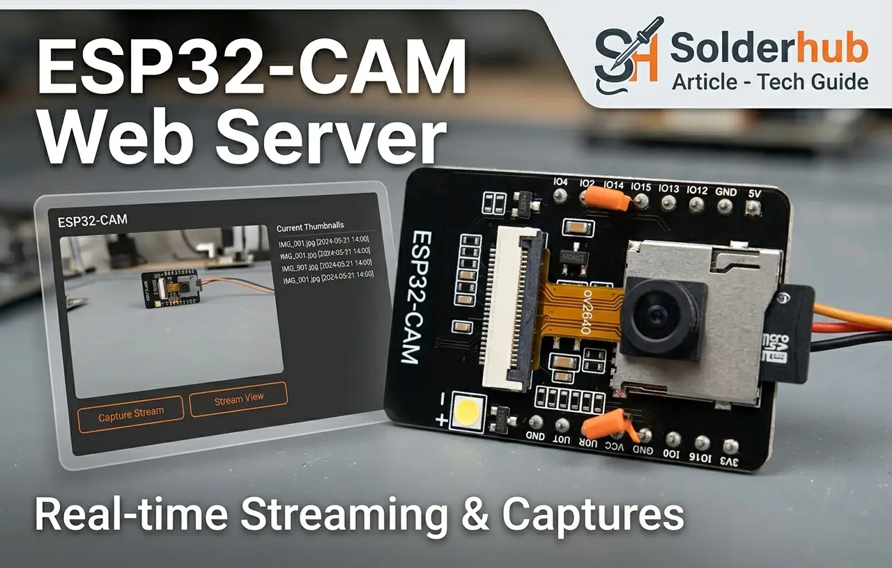
The ESP32-CAM is one of the cheapest ways to get a working video stream onto a local network, but the low price comes with a few rough edges that aren't mentioned on the product listing: there's no USB port, no onboard programmer, and the board is genuinely picky about power. Most of the frustration people report with this board — random reboots, a camera that refuses to initialize, uploads that fail halfway through — traces back to one of those two issues rather than anything wrong with the code.
This guide covers the complete setup end to end: wiring the board to an external FTDI programmer (or the plug-in ESP32-CAM-MB baseboard, covered as an alternative), configuring the Arduino IDE correctly, flashing and modifying the official CameraWebServer example, and resolving the handful of failure modes that account for nearly every reported problem with this hardware. By the end, you'll have a stable MJPEG stream reachable from any browser on your network, along with a clear understanding of why each configuration step matters rather than a sketch copied without context.
What You're Actually Building
The ESP32-CAM (specifically the AI-Thinker variant, which is what almost everyone means when they say "ESP32-CAM") pairs an ESP32-S chip with an OV2640 camera sensor and a microSD card slot on a single small board. Once flashed, it runs a tiny web server that does two things: serves a live MJPEG video stream at a URL like http://192.168.1.50/, and exposes a still-capture endpoint for grabbing single JPEGs. There's no h.264 encoding, no audio, and no companion app — it's a raw, low-latency video feed over your local network, which is exactly what you want for a garage cam, a 3D printer monitor, a birdfeeder cam, or a doorbell prototype.
The tradeoff for that simplicity is stability. This board pulls real current when the flash LED or camera sensor kicks in, and the onboard 3.3V regulator is marginal at best. Most of the "random reboot loop" complaints you'll read about trace back to power, not code, and I'll cover exactly how to avoid that below.
Hardware You'll Need
There are two common ways to get code onto this board: an external FTDI programmer wired by hand, or a plug-in ESP32-CAM-MB baseboard that handles the wiring for you. Pick one — you don't need both. The table below covers the FTDI path; the MB board is listed as a drop-in alternative to the FTDI/jumper/button rows.
| Item | Notes |
|---|---|
| AI-Thinker ESP32-CAM board | The gray PCB with the camera on a small ribbon cable. Other ESP32-CAM variants exist but pinouts differ. |
| FTDI USB-to-serial programmer (5V/3.3V) | You cannot program this board over USB directly — it has no USB port. A CP2102 or FT232-based adapter works fine. |
| 5V power supply capable of 500mA+ | A phone charger and a decent USB cable is usually enough. Powering from a laptop's USB port during flashing often isn't. |
| Jumper wires (female-female, 6 minimum) | For connecting the FTDI adapter to the board. |
| A push-button or a jumper wire (optional but recommended) | Makes putting the board into flashing mode far less annoying than shorting pins with a wire every time. |
| microSD card (optional) | Only needed if you want to save snapshots or timelapse frames locally later. |
| — or — ESP32-CAM-MB programmer baseboard | Replaces the FTDI adapter, jumper wires, and pushbutton rows above. The ESP32-CAM module clips directly onto this board, which connects to your computer over a regular USB cable and has its own onboard USB-to-serial chip (usually CH340 or CP2102) plus reset/IO0 buttons. No soldering or loose jumpers. |
One thing worth saying plainly: don't try to power this board directly from the FTDI adapter's 5V pin while also expecting stable camera operation. Most cheap FTDI boards can only supply 50–100mA on their 5V line, and the camera sensor alone can spike well past that during initialization. Use a separate 5V supply for power, and only use the FTDI adapter's TX/RX/GND lines for programming.
Option A: Wiring the FTDI Programmer to the ESP32-CAM
This is where most first attempts go sideways, mostly because the silkscreen labels on cheap boards are inconsistent. Here's the wiring that actually works:
| FTDI Adapter | ESP32-CAM |
|---|---|
| GND | GND |
| 5V | 5V (for power, separate from the wiring below if possible) |
| TX | U0R (RX) |
| RX | U0T (TX) |
Notice TX goes to RX and RX goes to TX — this is the one wire-crossing everyone forgets at least once. If your stream shows garbage in the serial monitor, or nothing at all, check this first before assuming the board is dead.
You'll also need to bridge GPIO0 to GND during the upload process — this puts the ESP32 into flashing mode instead of booting the existing firmware. There's no dedicated flash button on the base AI-Thinker board, so a lot of people just touch a jumper wire between those two pins at the right moment. It works, but it's fiddly. If you're going to be flashing this board more than once (and you will be, while debugging), soldering a small momentary push-button between GPIO0 and GND saves a genuine amount of frustration.
Option B: Using the ESP32-CAM-MB Baseboard
The ESP32-CAM-MB is a small carrier board the ESP32-CAM module clips onto — it puts a USB-to-serial chip (usually CH340 or CP2102) and the reset/IO0 buttons that the bare module lacks onto one board, so there's no hand-wiring at all.
- Clip the ESP32-CAM module onto the MB baseboard, matching the pin header orientation printed on the silkscreen — it only lines up one way.
- Plug the MB board into your computer with a standard USB cable (micro-USB on most versions).
- Install the CH340 or CP2102 driver if your OS doesn't detect the port automatically (Windows especially may need this on first use) — check Device Manager (Windows) or
ls /dev/tty.*(Mac/Linux) for a new serial port after plugging in. - In the Arduino IDE, select that new port under Tools → Port, keeping Tools → Board set to AI Thinker ESP32-CAM as before.
The board settings, partition scheme, and sketch are identical to the FTDI path — the only thing that changes is how you get power and serial data to the module. Skip ahead to Setting Up the Arduino IDE below; everything from there on is the same for both options.
Setting Up the Arduino IDE
If you've never added ESP32 support to the Arduino IDE before, here's the short version:
- Open File → Preferences, and in "Additional Board Manager URLs" add:
https://raw.githubusercontent.com/espressif/arduino-esp32/gh-pages/package_esp32_index.json - Open Tools → Board → Boards Manager, search for "esp32", and install the package by Espressif Systems.
- Under Tools → Board, select AI Thinker ESP32-CAM.
- Set Partition Scheme to "Huge APP (3MB No OTA/1MB SPIFFS)" — this matters more than people expect, because the camera web server sketch is large enough that the default partition scheme will fail to compile with an "out of program storage space" error.
- Set upload speed to 115200. Higher speeds sound tempting but cause more failed uploads on this board than they're worth.
That partition scheme setting trips people up constantly — if your sketch compiles fine on other ESP32 boards but throws a size error on this one, that's almost always the cause.
Loading and Modifying the CameraWebServer Sketch
Espressif ships an example sketch that does almost everything you need out of the box: File → Examples → ESP32 → Camera → CameraWebServer. Don't rewrite this from scratch — it already handles the trickiest part, which is initializing the OV2640 sensor with the correct pin mapping for this exact board.
Two changes are required before it'll work on your network:
// Near the top of the sketch
const char* ssid = "YOUR_WIFI_NAME";
const char* password = "YOUR_WIFI_PASSWORD";
And make sure the camera model is uncommented correctly — this is the second most common cause of a black screen or "camera init failed" error:
// Select camera model
#define CAMERA_MODEL_AI_THINKER // Has PSRAM
Every other camera model definition in that block should stay commented out. If you copy a sketch from a tutorial written for a different board, this line is usually the first thing to check.
Complete Configuration Reference
For reference, here is the full block of configuration values relevant to this build, consolidated in one place. These lines appear at different points in the CameraWebServer sketch, but reviewing them together makes it easier to confirm nothing was missed before compiling:
// ===== Network credentials =====
const char* ssid = "YOUR_WIFI_NAME";
const char* password = "YOUR_WIFI_PASSWORD";

// ===== Camera model selection =====
// Only ONE of these should be uncommented.
// The AI-Thinker board requires this exact definition:
#define CAMERA_MODEL_AI_THINKER   // Has PSRAM

// ===== AI-Thinker pin mapping (already defined in camera_pins.h) =====
// Included here for reference only -- do not add manually,
// it is pulled in automatically once CAMERA_MODEL_AI_THINKER is set.
#define PWDN_GPIO_NUM     32
#define RESET_GPIO_NUM    -1
#define XCLK_GPIO_NUM      0
#define SIOD_GPIO_NUM     26
#define SIOC_GPIO_NUM     27
#define Y9_GPIO_NUM       35
#define Y8_GPIO_NUM       34
#define Y7_GPIO_NUM       39
#define Y6_GPIO_NUM       36
#define Y5_GPIO_NUM       21
#define Y4_GPIO_NUM       19
#define Y3_GPIO_NUM       18
#define Y2_GPIO_NUM        5
#define VSYNC_GPIO_NUM    25
#define HREF_GPIO_NUM     23
#define PCLK_GPIO_NUM     22

// ===== Frame size and quality on boot =====
// Set inside app_httpd.cpp's camera config struct, or adjusted
// live from the control page after boot:
config.frame_size = FRAMESIZE_VGA;   // Recommended starting point
config.jpeg_quality = 10;            // Lower number = higher quality, larger frames
config.fb_count = 2;                 // Requires PSRAM; enables smoother streaming
The pin mapping block doesn't need to be typed in manually — it's pulled in automatically from camera_pins.h once the correct CAMERA_MODEL_AI_THINKER definition is active. It's included above so you can confirm, if you're debugging a persistent camera-init failure, that the pin assignments match your board rather than a different ESP32-CAM variant with a different sensor wiring layout.
The GPIO0 Flashing Dance
If you're using the FTDI path (Option A), here is the sequence that reliably gets code onto this board:
- With the board unpowered, connect GPIO0 to GND.
- Power on the board (or press reset if it's already powered).
- In the Arduino IDE, hit Upload.
- Watch the console — once you see "Connecting....." you're in the flashing handshake.
- Once the upload finishes and you see "Hard resetting via RTS pin" (or similar), disconnect GPIO0 from GND.
- Press the reset button (or power-cycle) to boot into normal mode.
If the IDE sits on "Connecting....." and eventually times out, GPIO0 usually was not grounded at the right moment, or the TX/RX wires are swapped. A defective board is a rare cause of this error; wiring and timing account for the overwhelming majority of failed upload attempts.
If you're using the ESP32-CAM-MB baseboard (Option B): try hitting Upload first — many MB boards handle reset and flashing automatically, with no button-pressing needed. If the IDE times out on "Connecting.....", the board doesn't have auto-program circuitry, so do it manually: hold down the IO0 button, tap RST once while still holding IO0, then release IO0 and hit Upload in the IDE. It's the same handshake as the GPIO0-to-GND jumper trick above, just via the board's built-in buttons instead of a loose wire.
First Boot: Finding Your Stream
Once flashed and rebooted in normal mode, open the Serial Monitor at 115200 baud and watch for the board to connect to WiFi. It'll print something like:
WiFi connected
Camera Stream Ready! Go to: http://192.168.1.47
Type that IP into any browser on the same network — phone, laptop, doesn't matter — and you'll land on a simple control page with a "Start Stream" button and a pile of sliders for resolution, quality, brightness, and a handful of image effects. Click Start Stream and you should see live video within a second or two.
If the page loads but the stream never starts, that's almost always a power issue, not a code issue — see the troubleshooting section below.
Resolution, Quality, and What They Actually Cost You
The control page exposes a resolution dropdown that goes from QQVGA (160x120) up to UXGA (1600x1200) on boards with PSRAM, which the AI-Thinker module has. Higher isn't automatically better here — it's a direct tradeoff against frame rate and stability:
| Resolution | Typical Frame Rate | Best For |
|---|---|---|
| QVGA (320x240) | 20-25 fps | Motion detection, low-bandwidth monitoring |
| VGA (640x480) | 12-15 fps | General purpose monitoring, most home projects |
| SVGA (800x600) | 8-10 fps | Better detail when frame rate is less critical |
| UXGA (1600x1200) | 3-5 fps | Still captures, timelapses — too slow for smooth live video |
For most "watch my garage" or "watch my 3D printer" use cases, VGA at medium JPEG quality is the sweet spot. Cranking resolution up to UXGA for a live stream is a common first mistake — the frame rate drops so low it looks broken, when really it's just doing exactly what you asked it to.
Common Problems and How to Actually Fix Them
"Camera init failed with error 0x20001" in the serial monitor. This is a power problem in the overwhelming majority of cases, not a wiring or code problem. It means the camera sensor didn't get stable power during its startup sequence. Fix: use a proper 5V/1A+ supply, keep wires short, and if you're still seeing it, add a 100-470uF capacitor across the 5V and GND pins near the board. This single fix resolves the majority of "camera won't init" reports you'll find in forums.
Board resets itself repeatedly, especially when the flash LED fires. Same root cause — insufficient current. The onboard flash LED draws a real current spike, and a marginal power supply can't sustain it alongside the WiFi radio and camera sensor at the same time. A better power supply fixes this almost every time.
Stream loads but is extremely laggy or freezes after a few seconds. Usually a WiFi signal strength issue combined with too high a resolution setting. Try dropping to VGA and moving the board closer to your router to confirm.
Upload fails with "A fatal error occurred: Failed to connect to ESP32." GPIO0 wasn't grounded before power-on/reset, or your TX/RX lines are swapped. Double-check the crossover wiring from the earlier section.
Compilation fails with "Sketch too big." You forgot to set the Partition Scheme to "Huge APP" in the Tools menu — this is the single most common compile-time failure for this specific sketch.
Giving It a Static IP (So You're Not Guessing Every Reboot)
By default the board grabs whatever IP your router's DHCP hands out, which can change on reboot and makes bookmarking the stream annoying. Two ways to fix this, and I'd recommend the router-side one:
Option A — DHCP reservation on your router (recommended). Log into your router's admin page, find the DHCP client list, locate the ESP32-CAM's MAC address (printed in the serial monitor on boot), and reserve a fixed IP for it. This keeps the IP configuration out of your sketch entirely, which matters if you ever change networks.
Option B — Hardcode a static IP in the sketch. Add this before WiFi.begin():
IPAddress local_IP(192, 168, 1, 184);
IPAddress gateway(192, 168, 1, 1);
IPAddress subnet(255, 255, 255, 0);
WiFi.config(local_IP, gateway, subnet);
Just make sure the address you pick is outside your router's DHCP pool, or you risk two devices fighting over the same IP later.
What to Build Next
Once the base stream is working reliably, this same hardware supports a lot more than a browser tab:
- Motion-triggered captures to microSD — the camera driver library exposes a
esp_camera_fb_get()call you can wrap in a simple frame-differencing check to save snapshots only when something changes. - Home Assistant integration — Home Assistant's generic camera integration can pull this MJPEG stream directly using the board's IP, no extra hardware needed, which turns this into a real security camera dashboard tile in about five minutes.
- Timelapse recording — capture a still on an interval and write it to SD with a timestamped filename, then stitch the sequence into a video afterward with ffmpeg on your computer.
- Basic face or motion detection — the newer Espressif camera examples include on-device detection models, though performance is limited on this chip and it's better suited to "did something move" than reliable facial recognition.
Each of those is really its own project built on top of what you just got running, and starting from a stable, correctly-wired base stream makes all of them dramatically easier to debug than starting from scratch.
Wrap-Up
The difference between a reliable ESP32-CAM build and a frustrating one usually comes down to three factors: correct crossover wiring between the FTDI adapter and the board, a power supply capable of sustaining current under load, and the Huge APP partition scheme set before compiling. With those three addressed, the official CameraWebServer example is stable enough for long-term unattended use -- boards configured this way commonly run for months without intervention.
Given its low cost and capability, the ESP32-CAM is worth keeping on hand in multiples. Once the process has been done once, repeating it for additional cameras typically takes a fraction of the time the first build required.
A Word on Security Before You Point This at the Internet
The stock CameraWebServer sketch includes no authentication. Any device that can reach the board's IP address on the local network can view the stream without a login. On a home network with no ports forwarded externally, this is a reasonable risk for most users, since the WiFi password itself functions as the access control.
A common and inadvisable practice is forwarding the camera's port on the router to allow remote viewing from outside the network. This is not recommended with the unmodified sketch. For remote access, route the connection through a VPN back into the home network (WireGuard on a low-cost router or a Raspberry Pi is a straightforward option), or place the stream behind a reverse proxy with basic authentication enabled. Both approaches require additional setup time, but they close off exposure to automated scanning services that specifically index unsecured IP cameras -- a real and well-documented category of tool.
Frequently Asked Questions
Can I power this from a battery instead of a wall adapter? Yes, but budget for it properly -- a single-cell LiPo with a boost converter to 5V works, but the current draw during flash-LED and camera-init spikes (sometimes 300-500mA briefly) means a small battery will drain faster than the mAh rating suggests. For anything meant to run more than a few hours unattended, wall power is the far less frustrating option.
Why does the image look washed out or have a purple tint? This is almost always a sensor ribbon cable that's slightly loose or seated at an angle. Power down, gently reseat the camera ribbon into its connector making sure it's pushed in evenly, and power back up.
Can I run two of these on the same network? Yes, without any conflict, as long as each gets its own IP (see the static IP section above) and you bookmark each address separately. There's nothing in the sketch that assumes it's the only camera on the network.
Does this work over 5GHz WiFi? No -- the ESP32 series only supports 2.4GHz WiFi. If your router broadcasts a combined SSID, this generally isn't an issue since the ESP32 will negotiate 2.4GHz automatically, but on networks with separate 2.4GHz and 5GHz network names, make sure you're connecting it to the 2.4GHz one.