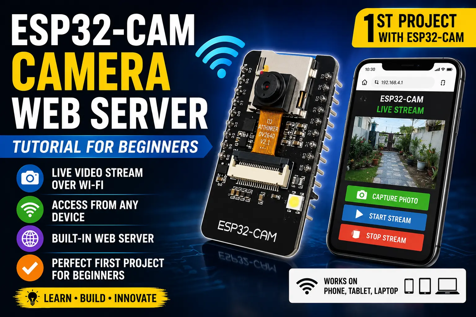
ESP32-CAM Camera Web Server Tutorial for Beginners
The ESP32-CAM has no USB port and needs an FTDI adapter to program. This guide walks through correct wiring of the programmer, the GPIO0 bootloader trick, flashing your first sketch, and blinking the onboard flash LED.
What the ESP32-CAM Actually Is
The AI Thinker ESP32-CAM is not a standalone dev board in the conventional sense — it is a module designed to be embedded into products. It combines an ESP32-S chip, 4 MB of PSRAM (for camera frame buffers), and a 2 MP OV2640 camera socket onto a 27 × 40 mm PCB.
What it deliberately leaves out: a USB port, a USB-to-serial bridge chip, a reset button, and any onboard programmer. This keeps the board small and cheap but means you cannot plug it into a computer and upload like you would with an Uno or a standard ESP32 dev kit.
What you get instead: the raw UART pins (GPIO1/TX and GPIO3/RX) and a bootloader mode triggered by pulling GPIO0 LOW at reset. Pair those with a cheap FTDI FT232RL adapter and you have a perfectly functional programmer.
The one built-in LED available without a camera is the white flash LED on GPIO 4 — a high-power SMD LED meant for illuminating subjects for the camera. It is bright enough to use as a simple indicator, though it draws significantly more current than a 5mm LED through a resistor.
🚨 Danger
The ESP32-CAM operates at 3.3V. The FTDI adapter MUST be set or jumpered to 3.3V — not 5V. Connecting a 5V FTDI adapter without the jumper set correctly will immediately damage the ESP32-CAM. Double-check the voltage jumper before powering up.
The GPIO Pin Situation
The ESP32-CAM has 16 accessible pins but most are consumed by the camera interface. What is left for user code:
- GPIO 0: boot-mode select — must be HIGH for normal run, LOW for bootloader. Has an onboard 10kΩ pull-up.
- GPIO 1 (TX) / GPIO 3 (RX): UART0 — used for programming and Serial Monitor. Shared with camera module.
- GPIO 4: white flash LED (onboard, high power). Also used as SD card DATA1 if using the SD card slot.
- GPIO 16: can be used as output. Often marked IO16 on the silkscreen.
- GPIO 2: general purpose. Shares with SD card DATA0.
The bottom line: the ESP32-CAM is not the board to choose if you need many free GPIO pins. It is the board to choose when you specifically need a camera plus WiFi in a small form factor.
Components required
FTDI Wiring — Get This Right First
Before connecting anything, set the FTDI adapter's voltage jumper to 3.3V. It is usually a 3-pin header with a jumper cap — move it to the 3.3V position.
| FTDI Adapter Pin | ESP32-CAM Pin | |------------------|---------------| | GND | GND | | VCC (3.3V) | 3.3V | | TX | GPIO3 (RX) | | RX | GPIO1 (TX) |
Note the cross: FTDI TX goes to ESP32-CAM RX, and FTDI RX goes to ESP32-CAM TX. This is correct — transmit on one side connects to receive on the other.
For upload mode: add one extra wire between GPIO 0 and GND. This pulls GPIO0 LOW, which tells the bootloader to accept incoming firmware. Remove this wire (or just unplug it from GPIO0) after uploading.
⚠️ Warning
The flash LED on GPIO 4 is driven by a transistor and can draw up to 300 mA. Do not leave it on continuously — it gets hot and will shorten the LED's life. For a simple blink demo it is fine; for a long-running indicator use a separate low-power LED on GPIO 16 through a 330Ω resistor.
// ── ESP32-CAM AI Thinker — Flash LED Blink ───────────────────────────────────
// The onboard white flash LED is on GPIO 4, driven HIGH-active via a transistor.
// GPIO 4 also shares with SD card DATA1 — avoid using SD in the same sketch.
//
// Upload procedure:
//   1. Wire FTDI to ESP32-CAM per the table above
//   2. Short GPIO0 → GND
//   3. Power the board (connect FTDI to USB)
//   4. Click Upload in IDE
//   5. After upload: remove GPIO0 → GND wire, then press reset (cycle power)
// ─────────────────────────────────────────────────────────────────────────────

#define FLASH_LED  4     // Onboard white flash LED
#define ON_MS    200     // Short flash — LED is bright and warm, keep cycles short
#define OFF_MS   800     // Long off period

void setup() {
  Serial.begin(115200);
  delay(1000);

  pinMode(FLASH_LED, OUTPUT);
  digitalWrite(FLASH_LED, LOW);  // Start with LED off

  Serial.println("ESP32-CAM AI Thinker — ready");
  Serial.printf("PSRAM found: %s
", psramFound() ? "YES (4MB)" : "NO");
  Serial.printf("Free heap:   %d bytes
", ESP.getFreeHeap());
}

void loop() {
  // Short bright flash
  digitalWrite(FLASH_LED, HIGH);
  Serial.println("FLASH ON");
  delay(ON_MS);

  digitalWrite(FLASH_LED, LOW);
  Serial.println("flash off");
  delay(OFF_MS);
}
Board Settings in Arduino IDE
Select these exactly:
- Board: AI Thinker ESP32-CAM
- Upload Speed: 115200 (some adapters are unstable at higher speeds)
- Flash Mode: DIO
- Flash Size: 4MB (32Mb)
- Partition Scheme: Huge APP (3MB No OTA/1MB SPIFFS) — needed for camera code later
- Core Debug Level: None
- Port: your FTDI COM port
If the AI Thinker board does not appear in the board list, you need to install the ESP32 board package first (same URL as for the WROOM-32 in the previous guide).
Steps
- 1Set FTDI adapter jumper to 3.3V — visually confirm before connecting
- 2Wire FTDI to ESP32-CAM: cross TX/RX, share GND, supply 3.3V
- 3Add a short jumper between GPIO0 and GND (bootloader mode)
- 4Plug FTDI into USB — the COM port for the FTDI should appear in IDE
- 5Select board: AI Thinker ESP32-CAM, port: FTDI COM port, speed: 115200
- 6Click Upload — you should see 'Connecting......' then progress bars
- 7After 'Done uploading': remove the GPIO0→GND wire, then unplug and replug USB
- 8Open Serial Monitor at 115200 baud — the flash LED should blink and messages appear
Common Upload Failures
A fatal error: Failed to connect to ESP32: Timed out waiting for packet header
Most common cause: GPIO0 is not LOW when the upload starts. Make sure the jumper is firmly seated between GPIO0 and GND, then power-cycle the board (unplug/replug USB) and immediately click Upload again.
Wrong boot mode detected (0x13)!
The GPIO0 jumper was removed or loose before the upload started. Replace it and retry.
Garbage in Serial Monitor
The baud rate in the monitor does not match Serial.begin(115200). Set the monitor dropdown to 115200.
Board resets repeatedly (watchdog) A leftover camera init call in the sketch may be crashing without a camera connected. The minimal blink sketch above has no camera code so this should not happen.