
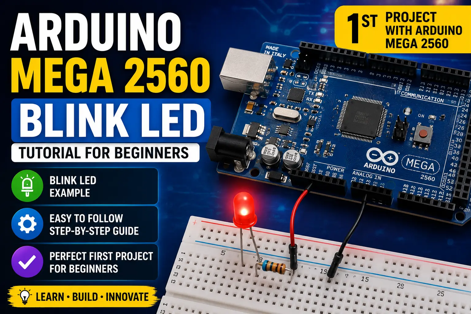
The Mega vs the Uno — When Does the Extra Hardware Matter?
The Arduino Mega 2560 runs the same AVR architecture as the Uno but on a much bigger chip: the ATmega2560. The core differences that actually matter in practice:
| Feature | Uno R3 | Mega 2560 |
|---|---|---|
| Flash memory | 32 KB | 256 KB |
| SRAM | 2 KB | 8 KB |
| Digital I/O | 14 | 54 |
| PWM pins | 6 | 15 |
| Analog inputs | 6 | 16 |
| Hardware UARTs | 1 | 4 |
| I2C buses | 1 | 1 |
| SPI buses | 1 | 1 |
The Uno is the right choice for 80% of projects. Reach for the Mega when you genuinely run out of pins or flash — large LED matrix projects, CNC controllers (GRBL + RAMPS), 3D printers (Marlin firmware), or anything that needs multiple independent serial ports simultaneously.
Board Layout
The Mega is physically larger (101.5 × 53.4 mm vs Uno's 68.6 × 53.4 mm) and has additional pin headers extending down both sides:
- Digital 0–13: same positions as Uno — compatible with most shields
- Digital 14–53: the extra pins, running down the sides
- PWM-capable pins: 2–13 and 44–46 (marked with ~)
- Analog A0–A15: on the right side header
- Four UART pairs: Serial (0/1), Serial1 (18/19), Serial2 (16/17), Serial3 (14/15)
- Power rail: same header as Uno — 3.3V, 5V, GND, VIN
One thing that catches people: the Mega uses a USB-B connector just like the Uno, but the USB-to-serial chip is the ATmega16U2 on R3 boards. The board is powered fine from USB.
💡 Tip
Mega shields are physically compatible with Uno shields as long as the shield only uses pins 0–13 and A0–A5. Some Uno shields block the extra Mega headers physically — check the shield dimensions before stacking.
Components
6 itemsNeed these parts? Get this build sheet by email
Parts list with buy links, plus new builds as they're published. By subscribing you agree to our Privacy Policy. Unsubscribe anytime.
Wiring — Three LEDs on Pins 22, 23, 24
We will use three of the Mega-only digital pins to make this distinct from the Uno exercise:
- LED 1 anode → 220 Ω → pin 22, cathode → GND
- LED 2 anode → 220 Ω → pin 23, cathode → GND
- LED 3 anode → 220 Ω → pin 24, cathode → GND
These pins sit on the right-side header that the Uno does not have. Any of pins 22–53 work identically for basic digital output.
IDE Setup for Mega
In Arduino IDE 2, the only change needed versus the Uno workflow is the board selection:
Tools → Board → Arduino AVR Boards → Arduino Mega or Mega 2560
Then set Tools → Processor → ATmega2560 (the 1280 variant is a much older, rarer board).
The port selection is the same process. Upload speed defaults to 115200 baud for the Mega, which is faster than the Uno's 115200 — uploads complete noticeably quicker because of the larger flash.
Steps
- 1Select board: Arduino Mega or Mega 2560 → Processor: ATmega2560
- 2Wire three LEDs through 220Ω resistors to pins 22, 23, 24
- 3Upload the chase sketch — LEDs should run forward and backward
- 4Open Serial Monitor at 9600 baud to confirm the startup message prints
- 5Try adding a 4th LED on pin 25 — extend the LEDS array and reupload
- 6Notice the upload is fast — 256 KB flash, but code transfer is quick at 115200 baud
RFID Reader Wiring and Card Enrollment
The MFRC522 reader uses SPI and is a 3.3 V device. Connect its SDA/SS, SCK, MOSI, MISO, and RST pins to the SPI and reset pins defined in the sketch, then connect 3.3 V and GND. On an Arduino Uno, do not power the MFRC522 from 5 V and do not drive its signal pins with 5 V logic unless the specific breakout explicitly includes level shifting. Use a compatible logic-level shifter where required. The label SDA on this module usually means SPI chip select, not I²C data.
| Signal | Uno R3 common SPI pin | Notes |
|---|---|---|
| SCK | D13 | SPI clock |
| MOSI | D11 | Controller to reader |
| MISO | D12 | Reader to controller |
| SS/SDA | D10, if used by sketch | SPI chip select |
| RST | Pin defined in sketch | Reset |
| VCC | 3.3 V | Do not use 5 V |
| GND | GND | Common reference |
Use the actual sketch pin definitions if they differ from this common mapping. Read a card UID during setup and enroll only test cards you control. Store the UID list in a clear, documented format and provide a way to remove a card when access should be revoked.
Security Limitations
A basic MFRC522 UID check is a learning demonstration, not a secure access-control system. Card identifiers can be copied or emulated on some card types, and UID-only authorization does not provide strong cryptographic authentication. Do not use this design as the sole lock for a home, workplace, or anything that protects people or valuable property. A real access system needs secure credentials, protected key storage, audit controls, and a fail-safe mechanical design.
Keep the lock actuator on a suitable transistor or relay driver; never power a solenoid or lock directly from an Arduino GPIO. Use a separate supply rated for the actuator's current and protect inductive loads with an appropriate flyback path. Decide what the lock should do during power loss and controller reset, and test that behavior before attaching the mechanism to a door.
Test Procedure and Troubleshooting
- Test reader detection and card UID output before connecting the lock.
- Verify that an enrolled test card is accepted and an unknown card is rejected.
- Confirm that the lock output returns to its safe state after the activation interval.
- Test repeated scans, reset, and power cycling.
- If the reader is not detected, check 3.3 V supply, SPI pin mapping, reset wiring, and logic levels.
- If the reader works only intermittently, shorten SPI wires and check for supply noise.
The access log can help with a classroom demonstration, but avoid storing personal data unnecessarily. For any real deployment, obtain appropriate consent and review privacy and physical-security requirements.
Ultrasonic Sensor Wiring and Distance Calculation
For a common HC-SR04 module, connect VCC to its rated 5 V supply, GND to Arduino GND, and TRIG and ECHO to the digital pins defined in the sketch. The Uno can accept the sensor's 5 V ECHO signal directly; 3.3 V boards such as many ESP32 variants generally require a divider or level shifter on ECHO. Check the exact sensor version before wiring.
The sensor estimates distance by timing the ultrasonic echo. A common approximation in air at room temperature is distance in centimetres equals echo pulse duration in microseconds divided by about 58. This is an estimate: temperature, target angle, surface material, and sensor blind zones affect the reading. Take multiple samples and reject timeouts instead of treating a missing echo as a real distance.
Set Practical Warning Thresholds
Choose warning and stop distances based on the vehicle's speed and the sensor's real mounting position. A small toy vehicle needs a larger stopping margin than the sensor's measurement error alone suggests. Add hysteresis between warning-on and warning-off thresholds so the buzzer or indicator does not chatter when the distance fluctuates near the boundary. A parking sensor is an aid, not a substitute for direct observation.
Installation and Troubleshooting
- Test the sensor stationary with a flat target at several known distances.
- Keep the sensor face clear of the chassis and ensure it points straight toward the target.
- Check that TRIG and ECHO match the code and that the ground connection is secure.
- If readings jump, inspect loose wires, angled targets, soft materials, and electrical noise from motors.
- If no echo is received, use a timeout and display an explicit out-of-range state rather than an arbitrary zero distance.
- Test the buzzer or LED independently before integrating the full alert logic.
Mount the module rigidly and protect its electronics from rain unless the particular sensor is rated for outdoor use. If this project is fitted to a moving vehicle, test at walking speed in an open area first and do not depend on a single ultrasonic sensor for collision avoidance.
Sensor Differences and Wiring
The DHT22 measures temperature and relative humidity; the BMP280 measures temperature and atmospheric pressure but not humidity. Combining them provides humidity from the DHT22 and pressure plus a second temperature reading from the BMP280. Treat the two temperature readings as separate measurements because sensor placement, response time, and self-heating can make them differ.
For the BMP280 I²C interface on an Arduino Uno, connect SDA to A4 and SCL to A5. Connect the DHT22 data output to the digital pin configured in the sketch, and follow the sensor breakout's supply requirements. Bare sensor modules may not tolerate the same voltage as breakout boards with regulators or level shifters. If using a bare DHT22, it typically requires a pull-up resistor on the data line; many modules already include one.
Measurement Quality
Place the sensors away from the Uno regulator, direct sunlight, warm displays, and drafts from fans if the goal is to measure room conditions. Give the sensors time to settle after power-up. Do not compare a newly powered sensor's first reading directly with a stabilized reference instrument. For pressure, record units and remember that weather changes and elevation both affect the reading.
Validation and Troubleshooting
- Confirm the BMP280 is detected at its I²C address, commonly 0x76 or 0x77.
- Confirm the DHT library is configured for the correct sensor model and data pin.
- Check that the BMP280 is not actually a BMP180 or another visually similar module.
- If readings are NaN or absent, inspect pull-ups, supply voltage, wiring, and library initialization.
- Compare temperature and humidity with a reference device after allowing both to stabilize.
- Use a reasonable sampling interval; the DHT22 should not be polled too rapidly.
This station is suitable for learning sensor integration and displaying environmental trends. It should not be described as a calibrated weather instrument unless it has been compared with traceable references and installed in an appropriate radiation-shielded enclosure.
LED Wiring and Current Limiting
Connect each LED through its own current-limiting resistor. Do not connect an LED directly between a GPIO and ground. The resistor value depends on the LED forward voltage and desired current; for a simple indicator, a few milliamps is usually enough. Confirm the pin numbers in the sketch and ensure they are all configured as outputs. The Mega 2560 has more digital pins than the Uno, but each pin still has current limits and the board has an overall current budget.
| Circuit part | Connection guidance |
|---|---|
| LED anode | Digital output through a resistor |
| LED cathode | GND, if using active-high wiring |
| Resistor | One per LED, typically selected for a few mA |
| Common ground | Connect all LED return paths to board GND |
For a longer LED strip or many LEDs, use a transistor or driver IC rather than drawing the combined load directly from GPIO pins. Check the board's official electrical limits before selecting current.
Timing and Pattern Changes
A basic LED chaser turns one output on at a time, waits, then advances to the next output. The delay controls the animation speed. If you add buttons, serial control, or sensors later, replace long blocking delays with a millis()-based timing loop so the microcontroller can respond while the pattern runs. Make sure the final LED returns to the first LED without indexing outside the configured pin array.
Test and Troubleshooting
- Test a single LED and resistor before wiring the full sequence.
- Verify LED polarity; the longer lead is commonly the anode, but check the part if leads have been trimmed.
- Confirm every LED has its own resistor and that no adjacent pins are accidentally shorted.
- If an LED stays on, inspect its pin mapping and whether the code sets the pin LOW between steps.
- If the pattern skips or behaves unpredictably, check the pin array length against the loop bounds.
- Test at a slow interval first, then increase speed after verifying the sequence.
This project teaches digital outputs, arrays, and timing. It can be extended with selectable patterns or speed control, but keep the current-limiting resistors and safe GPIO loading in place.
Relay Wiring and Boot-State Safety
The relay module must be compatible with the ESP32's 3.3 V GPIO logic and the load current. Some relay boards are active-low, and some do not reliably trigger from 3.3 V logic; confirm the module's input specification rather than assuming that any 5 V relay board will work. Power the relay coil from a suitable supply and connect the logic ground as required by the module. Never power a relay coil or household load directly from an ESP32 GPIO.
Set the output to its safe state as early as possible during startup, before connecting to Wi-Fi or a messaging service. Choose the default relay state deliberately and verify it during reset, brownout, firmware upload, and network loss. For lights and other mains-powered loads, use a properly rated enclosed module, appropriate fusing and strain relief, and qualified mains installation. Do not build or test mains wiring on a breadboard.
Network Control and Authentication
If the relay is controlled by a Telegram bot or another remote service, validate every incoming command and restrict control to authorized users or chat IDs. Do not publish bot tokens, Wi-Fi passwords, or private credentials in a public sketch. Store secrets outside shared source code and rotate any token that has been accidentally exposed. Report command success only after the controller has confirmed the output state.
A remote service can be unavailable, delayed, or duplicated. Keep the local output state and remote reported state synchronized, and decide what should happen when Wi-Fi drops. For safety-sensitive loads, remote connectivity should not bypass local interlocks or protection.
Test Plan
- Test relay input polarity with the load disconnected.
- Confirm startup and reset do not cause an unintended relay pulse.
- Verify the allowed user list rejects an unauthorized test account.
- Disconnect Wi-Fi and confirm the local relay behavior remains predictable.
- Reboot the ESP32 while the relay is commanded on and verify the chosen boot policy.
- Test with a low-voltage lamp or other safe load before any mains installation.
If the ESP32 resets when the relay changes state, check the relay supply, grounding, decoupling, and inductive interference. If the relay never changes state, inspect active-low logic, input compatibility, and the GPIO number. A reliable smart switch needs safe electrical design as well as working network code.